Automatic clamping device for workpieces

An automatic clamping and workpiece clamping technology, applied in positioning devices, metal processing machinery parts, clamping, etc., can solve the problems of low clamping efficiency and inability to realize automatic clamping of workpieces, so as to ensure quality, ensure follow-up processing quality, The center maintains a stable effect

Inactive Publication Date: 2015-12-23
WUXI NAIBO ROBOT TECH CO LTD
View PDF4 Cites 2 Cited by
  • Summary
  • Abstract
  • Description
  • Claims
  • Application Information

AI Technical Summary

Problems solved by technology

[0002] The machine tool needs to clamp the workpiece before processing the workpiece. The existing workpiece clamping device usually uses a peach-shaped chuck to fast

Method used


Image

  • Automatic clamping device for workpieces
  • Automatic clamping device for workpieces
  • Automatic clamping device for workpieces

Examples


Example Embodiment

[0010] The structure of the automatic grinder of the present invention will be further described below in conjunction with the drawings:

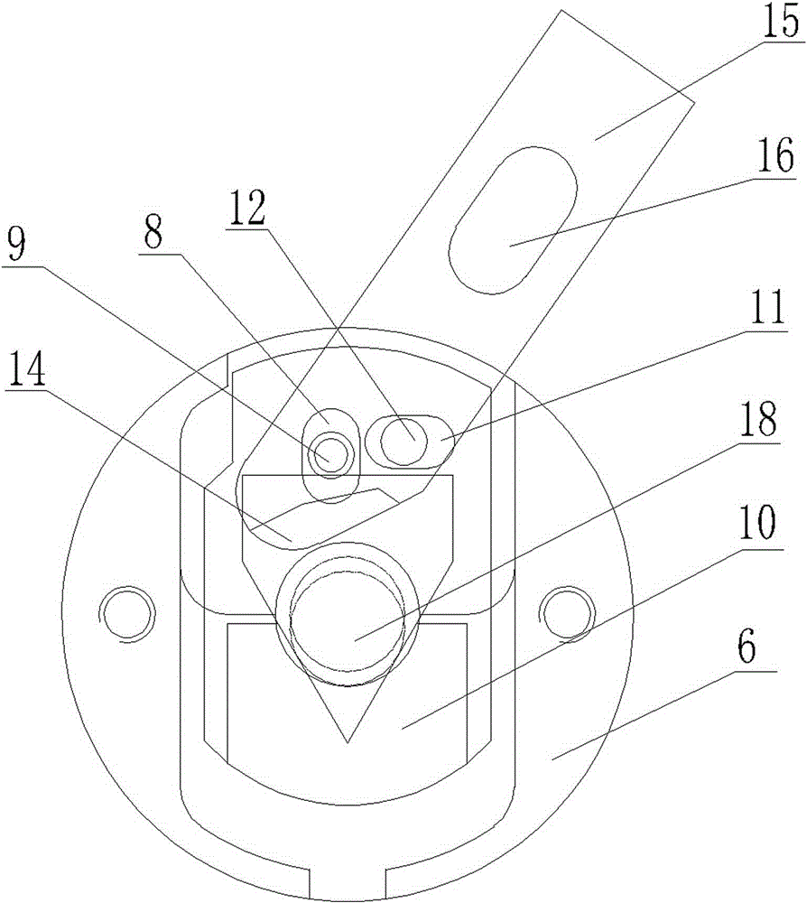
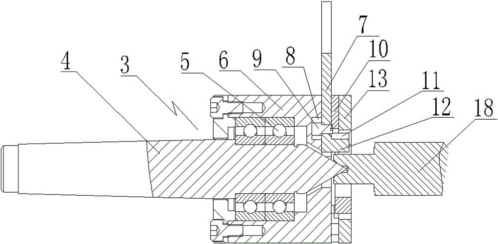
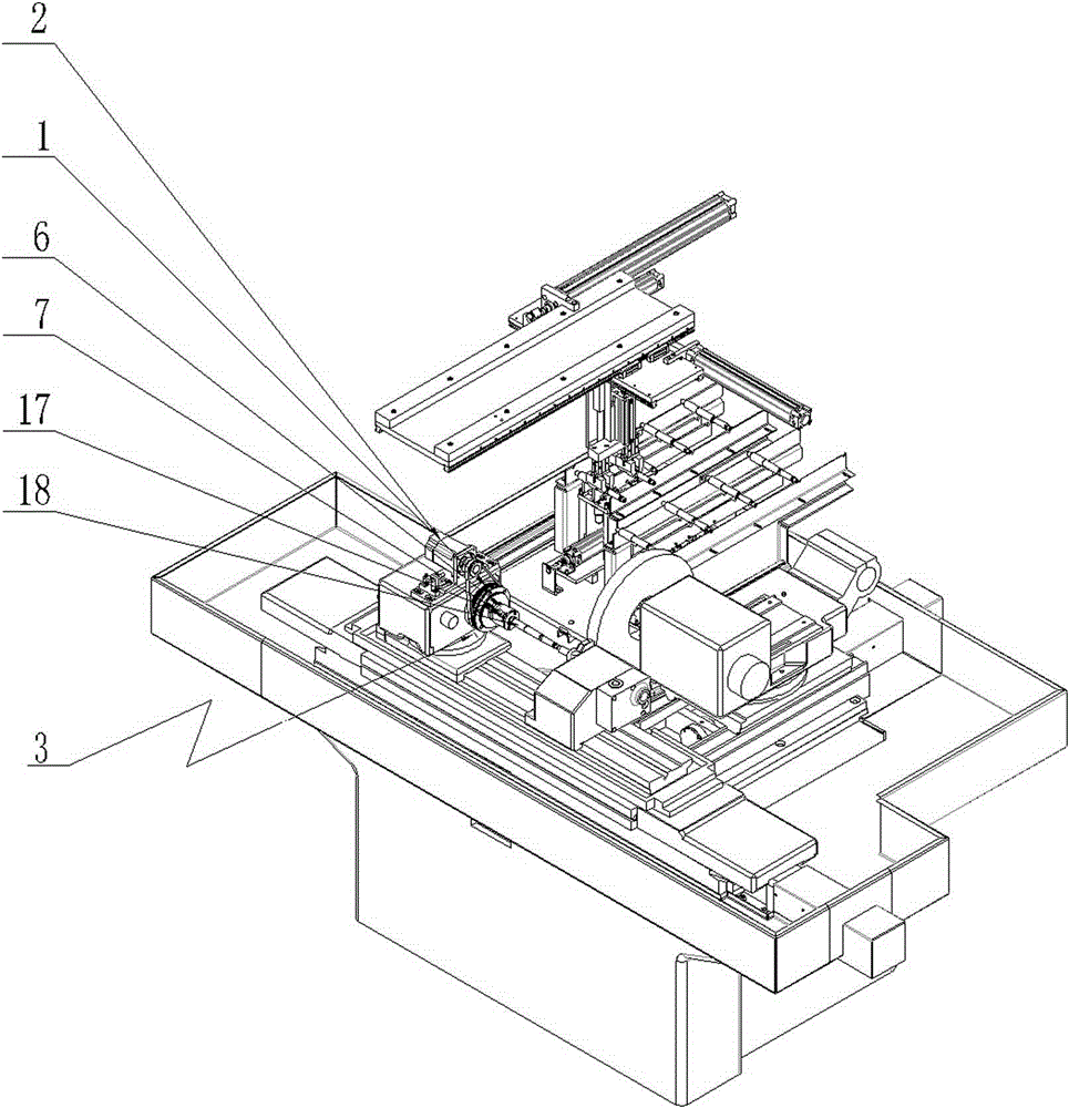
[0011] see figure 1 , figure 2 with image 3 , A workpiece automatic clamping device, comprising a top 4, the top 4 is connected to a base 6 through a bearing 5, the base 6 is movably connected to an eccentric pressing plate assembly 7, the base 6 is provided with a vertical elongated groove 8, and the eccentric pressing plate assembly 7 is arranged There is a first pin 9, the first pin 9 is matched with the vertical elongated slot 8, the eccentric pressing plate assembly 7 is movably connected to the V-shaped block 10, the V-shaped block 10 is provided with a horizontally elongated groove 11, and the eccentric pressing plate assembly 7 is arranged There is a second pin 12, the second pin 12 is matched with the horizontally elongated groove 13, the V-shaped block 10 is connected to the base 6 through the cover plate 14. The eccentric pressing...


PUM


Abstract

The invention provides an automatic clamping device for workpieces. Through the adoption of the clamping device disclosed by the invention, the clamping efficiency of clamping the workpieces is well improved, the automation of the workpiece clamping is realized, and besides, the clamping quality for the workpieces is also well guaranteed. The clamping device is characterized by comprising a clamping head structure, wherein the clamping head structure comprises a top; the top is connected with a base through bearings; an eccentric plate pressing assembly is movably connected to the base; a vertical long-shaped groove is formed in the base; a first pin is arranged on the eccentric plate pressing assembly; the first pin is matched with the vertical long-shaped groove; the eccentric plate pressing assembly is movably connected with a V-shaped block; a lateral long-shaped groove is formed in the V-shaped block; a second pin is arranged on the eccentric plate pressing assembly; the second pin is matched with the lateral long-shaped groove; the V-shaped block is connected with the base through a cover board; the eccentric plate pressing assembly comprises a fastening end and a driving end, wherein the fastening end is a bevel; the driving end is connected with the base; the fastening end is the bevel with a circular arc, and the driving end is connected with the base through cooperation between the long-shaped groove and the screw rod.

Description

technical field [0001] The invention relates to the technical field of machine tool automation, in particular to an automatic workpiece clamping device. Background technique [0002] The machine tool needs to clamp the workpiece before processing the workpiece. The existing workpiece clamping device usually uses a peach-shaped chuck to fasten and clamp the workpiece through bolts. This clamping chuck makes the clamping efficiency relatively high. Low, can not realize the automation of workpiece clamping. Contents of the invention [0003] Aiming at the deficiencies in the prior art, the present invention provides an automatic workpiece clamping device, which better improves the clamping efficiency of the workpiece clamping, realizes the automation of the workpiece clamping, and at the same time better ensures that the workpiece clamping quality. [0004] In order to achieve the above object, the present invention is achieved through the following technical solutions: an ...

Claims


Application Information

Patent Timeline
IPC IPC(8): B23Q3/06
CPCB23Q3/06
Inventor 毛新益曾宣飞
Owner WUXI NAIBO ROBOT TECH CO LTD
Why Eureka
Try Eureka