Automatic goods collecting trolley driven by potential energy

An automatic and small car technology, applied in the field of engineering applications, can solve the problems of low cost, laborious labor, energy shortage, etc., and achieve the effect of reasonable structure design, stable operation and convenient processing

Active Publication Date: 2015-12-23
KUNMING UNIV OF SCI & TECH
View PDF4 Cites 1 Cited by
  • Summary
  • Abstract
  • Description
  • Claims
  • Application Information

AI Technical Summary

Problems solved by technology

[0003] The technical problem to be solved by the present invention is: the present invention provides a potential energy-driven automatic pick-up trolley with low cost and high reliability to solve the problems of energy shortage and manual labor

Method used


Image

  • Automatic goods collecting trolley driven by potential energy
  • Automatic goods collecting trolley driven by potential energy
  • Automatic goods collecting trolley driven by potential energy

Examples


Embodiment 1

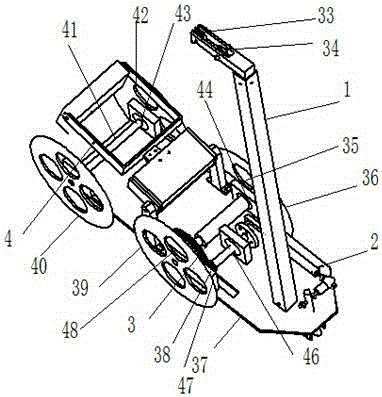
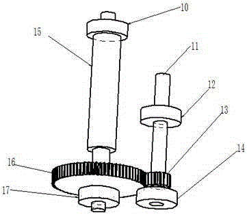
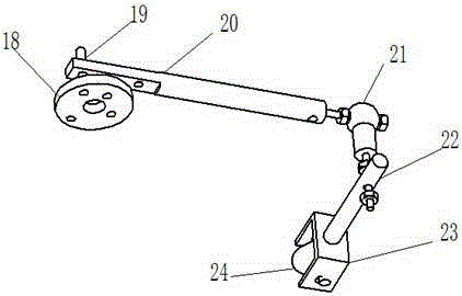
[0025] Example 1: as Figure 1-6 As shown, an automatic pickup trolley driven by potential energy includes a support mechanism 1, a steering mechanism 2, a transmission mechanism 3, and an automatic pickup mechanism 4; On the bottom plate 37 of 3, the steering mechanism 2 is connected with the driving shaft 11 of the transmission mechanism 3 through the turntable 18, the transmission mechanism 3 is fixed on the bottom plate 37 through the bearing seat, and the automatic pickup mechanism 4 is connected with the vertical support frame I25 and the vertical support frame II32. The bottom plate 37 of the transmission mechanism 3 is fixed.

Embodiment 2

[0026] Example 2: as Figure 1-6 As shown, an automatic pickup trolley driven by potential energy includes a support mechanism 1, a steering mechanism 2, a transmission mechanism 3, and an automatic pickup mechanism 4; On the bottom plate 37 of 3, the steering mechanism 2 is connected to the driving shaft 11 of the transmission mechanism 3 through the turntable 18, the transmission mechanism 3 is fixed on the bottom plate 37 through the bearing seat, and the automatic pickup mechanism 4 is connected with the vertical support frame I25 and the vertical support frame II32. The bottom plate 37 of the transmission mechanism 3 is fixed.

[0027] The support mechanism 1 includes an axis I5, an axis II6, a horizontal bracket 7, a support rod 8, a base 9, a fixed pulley I33, and a fixed pulley II34; , shaft II6 are connected with the horizontal bracket 7, the horizontal bracket 7 is connected with the support rod 8, the support rod 8 is connected with the base 9, and the base 9 is in...

Embodiment 3

[0028] Example 3: as Figure 1-6 As shown, an automatic pickup trolley driven by potential energy includes a support mechanism 1, a steering mechanism 2, a transmission mechanism 3, and an automatic pickup mechanism 4; On the bottom plate 37 of 3, the steering mechanism 2 is connected to the driving shaft 11 of the transmission mechanism 3 through the turntable 18, the transmission mechanism 3 is fixed on the bottom plate 37 through the bearing seat, and the automatic pickup mechanism 4 is connected with the vertical support frame I25 and the vertical support frame II32. The bottom plate 37 of the transmission mechanism 3 is fixed.

[0029] The support mechanism 1 includes an axis I5, an axis II6, a horizontal bracket 7, a support rod 8, a base 9, a fixed pulley I33, and a fixed pulley II34; , shaft II6 are connected with the horizontal bracket 7, the horizontal bracket 7 is connected with the support rod 8, the support rod 8 is connected with the base 9, and the base 9 is in...


PUM


Abstract

The invention relates to an automatic goods collecting trolley driven by potential energy, and belongs to the technical field of engineering application. The automatic goods collecting trolley comprises a supporting mechanism, a steering mechanism, a transmission mechanism and an automatic goods collecting mechanism. The supporting mechanism is fixedly connected to a bottom plate of the transmission mechanism through a supporting rod and a base. The steering mechanism is connected with a driving shaft of the transmission mechanism through a rotary disc. The transmission mechanism is fixed to the bottom plate through a bearing pedestal. The automatic goods collecting mechanism and the bottom plate of the transmission mechanism are fixed through a vertical supporting frame I and a vertical supporting frame II. The gravity potential energy can be adopted as driving force, the various mechanisms are reasonably utilized, an automatic goods collecting device is adopted, energy can be effectively saved, and part of manpower resources are saved.

Description

technical field [0001] The invention relates to an automatic picking-up trolley driven by potential energy, which belongs to the technical field of engineering application. Background technique [0002] In recent years, energy issues have begun to be paid more and more attention, and energy saving has become a topic in today's society. Today, most cars need energy to drive, and cars that do not need energy are urgently needed to be overcome; The method of picking up the goods manually, which is time-consuming and labor-intensive, and the production cost will also increase. Therefore, it is necessary to design a trolley that can use gravity as a driving force and use a robotic device to automatically pick up goods. SUMMARY OF THE INVENTION [0003] The technical problem to be solved by the present invention is: the present invention provides an automatic pickup trolley driven by potential energy, with low cost and high reliability, so as to solve the problems of energy sho...

Claims


Application Information

Patent Timeline
Patent Type & Authority Applications(China)
IPC IPC(8): B65G47/90
Inventor 孙伟停吴涛
Owner KUNMING UNIV OF SCI & TECH
Why Eureka
Try Eureka