
Cutter for lawn ventilator

A technology of ventilator and cutting tool, which is applied in lawn treatment machinery, agricultural machinery and implements, etc. It can solve the problems of gearbox damage, lithium battery pack damage, impact lithium battery pack, etc., so as to improve the service life and prolong the service life , Improve the effect of impact resistance

Pending Publication Date: 2019-01-29
CHANGZHOU CREATE ELECTRIC APPLIANCE
View PDF0 Cites 1 Cited by
  • Summary
  • Abstract
  • Description
  • Claims
  • Application Information

AI Technical Summary

Problems solved by technology

When in use, when the blade rotates and encounters hard objects such as stones on the grass, it will generate a huge impact, which will act on the output shaft of the gearbox through the rotating shaft, causing damage to the gearbox and the motor, and This structure is generally only used in grassland aerators driven by AC power. It is not suitable for grassland aerators driven by lithium batteries. Current changes will impact the lithium battery pack and cause damage to the lithium battery pack.

Method used


Image

  • Cutter for lawn ventilator
  • Cutter for lawn ventilator
  • Cutter for lawn ventilator

Examples


Embodiment 1)

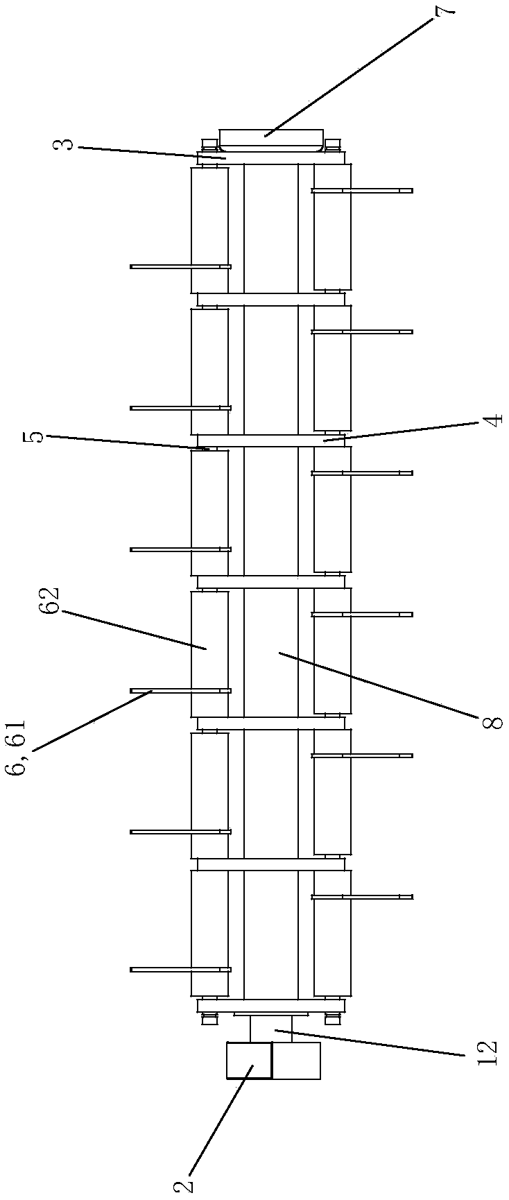
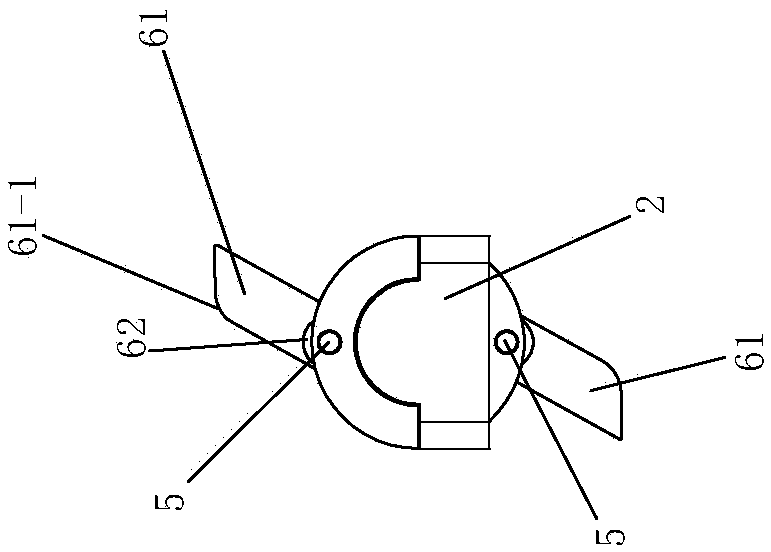
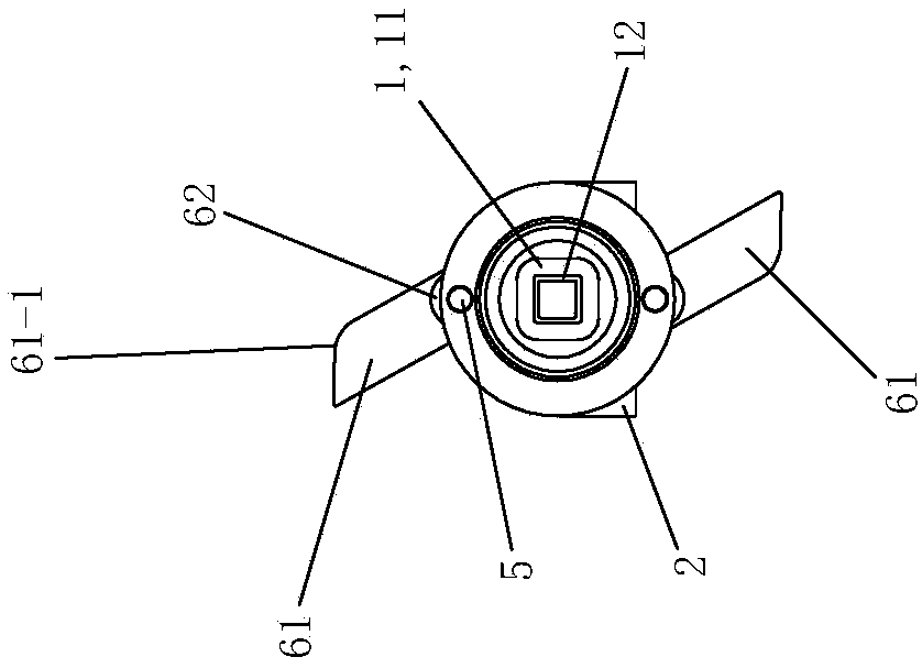
[0040] see Figure 1 to Figure 10 The cutter for a lawn ventilation machine of this embodiment includes a rotating shaft 1, a foot bracket 2, a mounting disk 3, a supporting disk 4, a cutter shaft 5, a blade assembly 6 and a dust cover 7.

[0041] see Figure 1 to Figure 6 The rotating shaft 1 is formed by connecting the long shaft 11 of the square tube and the short shaft 12 which is connected to the left end of the long shaft 11 of the square tube. When in use, the square output shaft of the gearbox of the grass ventilating machine is inserted into the right end of the long shaft 11 of the square tube, and the two are connected in a profile and form a detachable transmission connection for clearance fit. The left end of the stub shaft 12 is rotatably arranged in the foot bracket 2 through a corresponding bearing. The dust cover 7 is fixedly arranged on the right end of the long shaft 11 of the square tube, with the opening to the right, and is used to cover the corresponding p...

Embodiment 2)

[0047] see Picture 11 with Picture 12 The remaining parts of this embodiment are the same as the embodiment 1, and the difference is that: there are 11 support plates 4, and the 11 support plates 4 divide the long axis 11 of the square tube into 12 equal parts. There are 4 cutter shafts 5. The four cutter shafts are arranged at equal intervals along the circumferential direction of the long axis 11 of the square tube. Each section of each cutter shaft 5 is provided with blade assemblies 6 at intervals, and each cutter shaft 5 is provided with 3 sets of blade assemblies 6. The blades 61 on the four cutter shafts 5 are spiral in the axial direction of the long shaft 11 of the square tube Set up.

Embodiment 3)

[0049] The rest of this embodiment is the same as the embodiment 1, the difference is that: there are 15 support plates 4, and the 15 support plates 4 divide the long axis 11 of the square tube into 16 equal parts. There are 8 cutter shafts 5. The eight cutter shafts are arranged at equal intervals along the circumferential direction of the long axis 11 of the square tube. Each section of each cutter shaft 5 is provided with blade assemblies 6 at intervals, and each cutter shaft 5 is provided with 2 sets of blade assemblies 6. The blades 61 on the eight cutter shafts 5 are spiral in the axial direction of the long shaft 11 of the square tube Set up.


PUM


Abstract

The invention discloses a cutter for a lawn ventilator. The main points of the cutter provided by the invention are as follows: the cutter comprises a rotating shaft, a hitching leg support, mountingdisks, supporting disks, cutter shafts and blade assemblies; the left end of a short axis of the rotating shaft is rotatably arranged in the hitching leg support through a corresponding bearing; two mounting disks are respectively and fixedly arranged at the left and right ends of a square-tube long axis of the rotating shaft; the supporting disks are arranged on the square-tube long axis of the rotating shaft in a uniformly-spaced manner from left to right; the cutter shafts are arranged on the mounting disks and the supporting disks; each blade assembly comprises a blade and a connecting sleeve; each blade is fixedly embedded on a connecting sleeve; blades are rotatably arranged on the cutter shafts through connecting sleeves; and the blades are spirally arranged in the axial direction of the square-tube long axis of the rotating shaft.

Description

Technical field [0001] The invention relates to the field of garden tools, in particular to a knife used for a grass ventilation machine. Background technique [0002] The grass ventilation machine is used to improve the ventilation performance of the grass, which is beneficial to the growth of the grass. The tools of the grass ventilation machine include wire claws that clean up the fallen leaves and other garbage on the grass surface, and blades that loosen the soil on the grass surface. For the cutter assembly used on the existing grass ventilation machine, the blade and the rotating shaft are rigidly connected. The output shaft of the gearbox is the power input shaft of the tool device. The square output shaft of the gearbox and the square cavity of the rotating shaft are connected by a clearance fit transmission. When in use, when the blade encounters a hard object such as a rock on the grass, it will produce a huge impact. The impact will act on the output shaft of the g...

Claims


Application Information

Patent Timeline
Patent Type & Authority Applications(China)
IPC IPC(8): A01B45/02
CPCA01B45/026
Inventor 葛树兴陈坚跃张小荣丰新宇宋云健
Owner CHANGZHOU CREATE ELECTRIC APPLIANCE
Learn More