Eureka AIR delivers breakthrough ideas for toughest innovation challenges, trusted by R&D personnel around the world.

Rotary compressor and compression mechanism thereof

A technology of rotary compressor and compression mechanism, applied in the direction of rotary piston machinery, rotary piston pump, machine/engine, etc. The effect of reducing suction pressure pulsation, cost reduction, and reliability improvement

Active Publication Date: 2015-12-23
GUANGDONG MEIZHI COMPRESSOR +1
View PDF5 Cites 5 Cited by
  • Summary
  • Abstract
  • Description
  • Claims
  • Application Information

AI Technical Summary

Problems solved by technology

[0002] The cylinder suction structure of the existing rotary compressor generally has the suction hole on the cylinder. This design results in a suction closing angle of about 35 degrees. Only when the piston rotates through this angle from the slide groove, the piston will After closing the suction chamber and starting to compress, there will be suction backflow between 0° and the suction closing angle, resulting in a waste of the working volume of about 35°, which becomes the suction clearance volume, resulting in a decrease in the volumetric efficiency of the compressor. Under the condition of capacity, the displacement of the compressor must be increased, resulting in an increase in the cost of the compressor, a decrease in reliability, and a decrease in performance

Method used


Image

  • Rotary compressor and compression mechanism thereof
  • Rotary compressor and compression mechanism thereof
  • Rotary compressor and compression mechanism thereof

Examples


Embodiment Construction

[0032] Embodiments of the present invention are described in detail below, examples of which are shown in the drawings, wherein the same or similar reference numerals designate the same or similar elements or elements having the same or similar functions throughout. The embodiments described below by referring to the figures are exemplary only for explaining the present invention and should not be construed as limiting the present invention.

[0033] In describing the present invention, it should be understood that the terms "center", "longitudinal", "transverse", "length", "width", "thickness", "upper", "lower", "front", " Orientation indicated by rear, left, right, vertical, horizontal, top, bottom, inside, outside, clockwise, counterclockwise, etc. The positional relationship is based on the orientation or positional relationship shown in the drawings, which is only for the convenience of describing the present invention and simplifying the description, rather than indicati...


PUM


Abstract

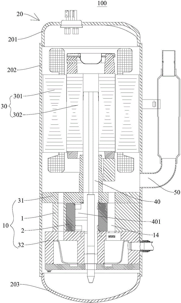
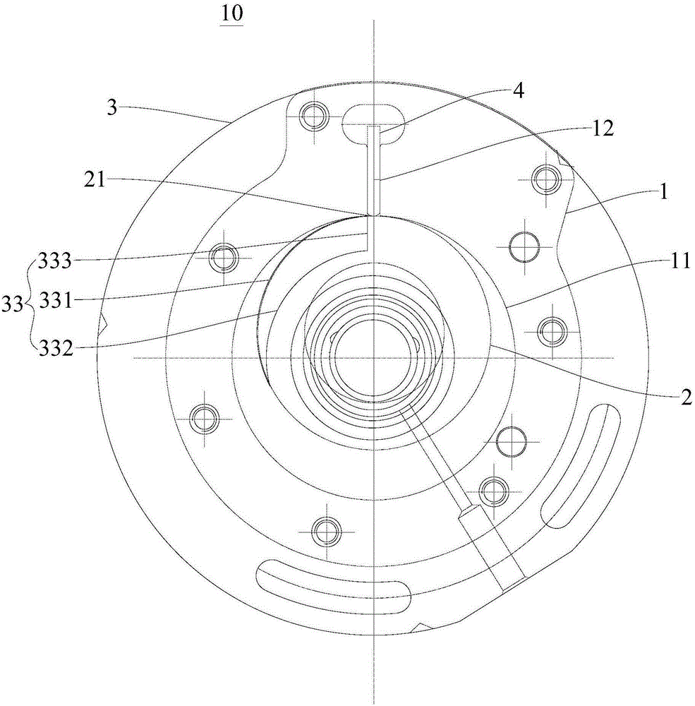
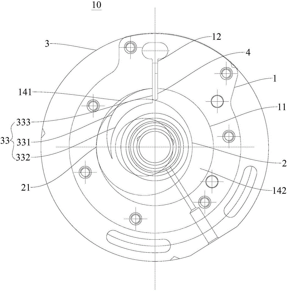
The invention discloses a rotary compressor and a compression mechanism thereof. The compression mechanism of the rotary compressor comprises an air cylinder, a piston and bearings, wherein the air cylinder is provided with an air cylinder hole and a sliding sheet groove; the piston is arranged on the eccentric part of a crankshaft in a sleeving way and can be eccentrically accommodated into the air cylinder hole around the center of the air cylinder hole; the bearings are arranged on the upper end and / or the lower end of the air cylinder; an air cylinder cavity is defined by the end faces of the bearings and the air cylinder hole together; at least one of the bearings is provided with an air suction hole; the air suction hole can be opened and closed by the end face of the piston to define the contact point of the piston and the air cylinder hole as the high point of the piston; when the high point of the piston is located in the middle of the opening of the sliding sheet groove, the end face of the piston closes the air suction hole; and when the high point of the piston is far away from the middle of the opening of the sliding sheet groove, the end face of the piston opens the air suction hole. The compression mechanism of the rotary compressor has the advantages that the volume efficiency is high; the cost is low; the performance is good; and the reliability is high.

Description

technical field [0001] The invention relates to the field of household appliances, in particular to a compression mechanism of a rotary compressor and a rotary compressor with the compression mechanism. Background technique [0002] The cylinder suction structure of the existing rotary compressor generally has the suction hole on the cylinder. This design results in a suction closing angle of about 35 degrees. Only when the piston rotates through this angle from the slide groove, the piston will After closing the suction chamber and starting to compress, there will be suction backflow between 0° and the suction closing angle, resulting in a waste of the working volume of about 35°, which becomes the suction clearance volume, resulting in a decrease in the volumetric efficiency of the compressor. Under the condition of capacity, the displacement of the compressor must be increased, resulting in an increase in the cost of the compressor, a decrease in reliability, and a decrea...

Claims


Application Information

Patent Timeline
IPC IPC(8): F04C18/356F04C29/00F04C29/12
Inventor 黎法运
Owner GUANGDONG MEIZHI COMPRESSOR
Why Eureka
Eureka Blog
Learn More