
Method and apparatus for controlling a material ejector system

A material and controller technology, which is applied in the direction of freight vehicles, vehicles with push plates, transport objects, etc., can solve the problems that materials cannot be spread evenly and increase the difficulty of vehicle operation

Active Publication Date: 2015-12-23
CATEPILLAR SARL
View PDF6 Cites 6 Cited by
  • Summary
  • Abstract
  • Description
  • Claims
  • Application Information

AI Technical Summary

Problems solved by technology

However, this requires the operator to carefully control the speed of the vehicle, which increases the difficulty of the vehicle's work
In addition, when the vehicle operator cannot maintain the speed of the vehicle, for example due to obstacles or slopes, the material can no longer be spread evenly

Method used


Image

  • Method and apparatus for controlling a material ejector system
  • Method and apparatus for controlling a material ejector system
  • Method and apparatus for controlling a material ejector system

Examples


Embodiment Construction

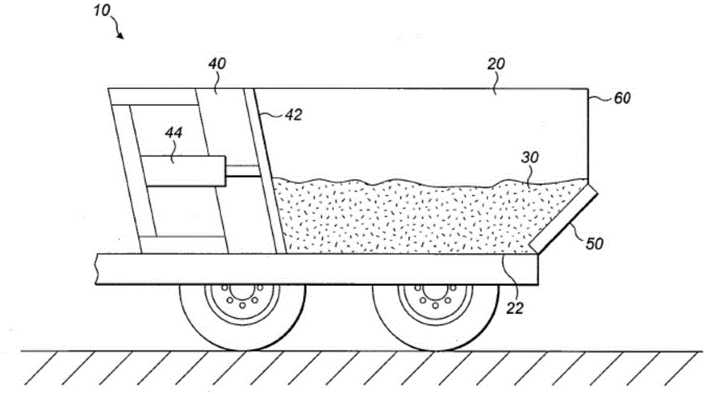
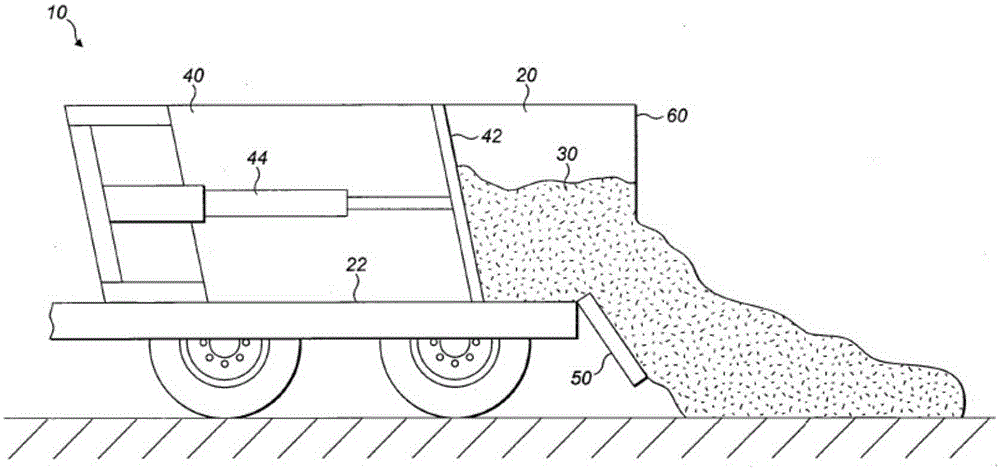
[0014] figure 1 Vehicle 10 is shown equipped with a material ejection system 40 for ejecting material 30 located in material container 20 . The vehicle 10 may be a vehicle with drive wheels (such as a truck), or a vehicle without drive wheels (such as a trailer designed to be towed by other vehicles with drive wheels). exist figure 1 In the configuration shown, the ejection of the material 30 in the material container 20 has not yet started. Thus, the door 50 is in the closed position to assist in retaining the material 30 in the material container 20, and the material ejection system 40 is in the initial position. As the vehicle 10 moves between fields, it can remain in a position such as figure 1 The configuration shown is such that material 30 remains in vehicle 10 .

[0015] The material pushing system 40 may include a push plate 42 and a multistage hydraulic cylinder 44, which is configured to move the push plate 42 from figure 1 The initial position shown in is move...


PUM


Abstract

The present disclosure relates to the spreading of a material (30) by pushing the material (30) from the back of a vehicle (10) using a material ejector system (40) whilst the vehicle (10) is moving. The depth of the spread material and how evenly it is spread is dependent on a number of factors that can be difficult and complicated for an operator of the vehicle (10) to control. In the present disclosure the speed at which the material is ejected from the vehicle (10) is set on the basis of a measured speed of the vehicle (10).

Description

technical field [0001] The invention relates to a method and a control device for controlling a material pushing and unloading system. Background technique [0002] Vehicles suitable for carrying material are discharged by raising the front end of the load zone so that the material slides down the load zone and is discharged from the rear of the vehicle. However, raising the load zone also raises the vehicle's center of gravity and, therefore, reduces the stability of the vehicle, making unloading unsafe when the vehicle is moving, especially on inclines, slopes or soft ground. Operation. [0003] Alternatively, the material can be pushed out of the vehicle using a push plate that moves along the load zone floor from the front to the rear, thereby pushing the material out of the rear of the vehicle. Since the operation of the dump mechanism does not raise the center of gravity of the vehicle, it is possible to dump material while the vehicle is moving. This is especially ...

Claims


Application Information

Patent Timeline
Patent Type & Authority Applications(China)
IPC IPC(8): B60P1/00
CPCB60P1/006
Inventor S·汤普森
Owner CATEPILLAR SARL
Learn More