Fuel injector nozzle plate

A fuel injection device and fuel injection technology, applied in the direction of fuel injection devices, charging systems, engine components, etc., can solve the problems of insufficient particle size, fuel is not easy to form a sharp liquid film, etc., and achieve an improved effect

Inactive Publication Date: 2015-12-23
ENPLAS CORP
View PDF8 Cites 0 Cited by
  • Summary
  • Abstract
  • Description
  • Claims
  • Application Information

AI Technical Summary

Problems solved by technology

As a result, the fuel injected from the nozzle hole 1003 of the nozzle plate 1002 is less likely to form a sharp liquid film, and the atomization by friction with air is insufficient.

Method used


Image

  • Fuel injector nozzle plate
  • Fuel injector nozzle plate
  • Fuel injector nozzle plate

Examples


no. 1 approach

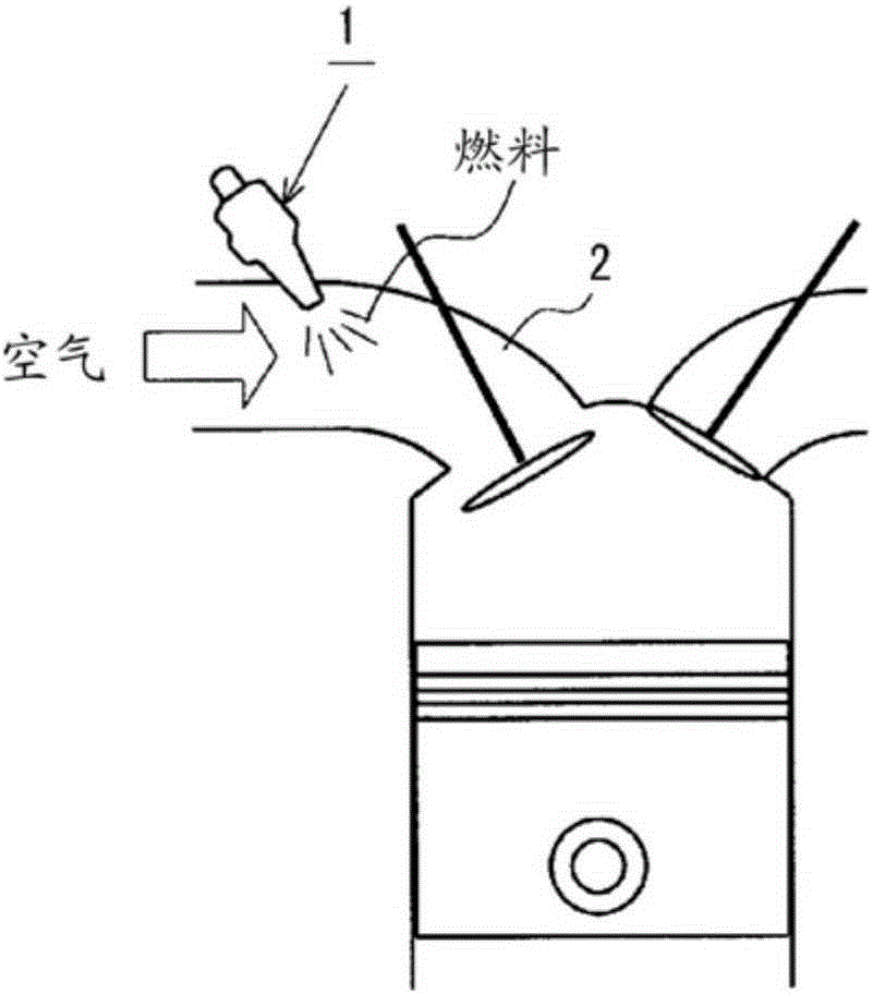
[0072] figure 1 It is a figure which schematically shows the usage state of the fuel injection apparatus 1 to which the nozzle plate for fuel injection apparatuses of this embodiment is attached. as it should figure 1 As shown, the port injection fuel injection device 1 is installed in the middle of the intake pipe 2 of the engine, injects fuel into the intake pipe 2, and mixes the air and fuel introduced into the intake pipe 2 to form a combustible mixture.

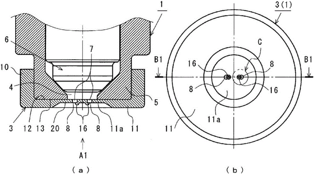
[0073] figure 2 It is a figure which shows the front-end side of the fuel injection apparatus 1 to which the nozzle plate 3 for fuel injection apparatuses (hereinafter referred to as a nozzle plate) is attached. also, figure 2 (a) is a front end side longitudinal sectional view of the fuel injection device 1 (along figure 2 (B1-B1 line B1-B1 cut off the cross-sectional view shown). in addition, figure 2 (b) is a bottom view of the front end side of the fuel injection device 1 (shown from figure 2 (a) A diag...

no. 2 approach

[0184] Figure 25 ~ Figure 27 It is an enlarged view showing a part of the nozzle plate 3 according to the second embodiment of the present invention. in, Figure 25 (a) is a plan view of the nozzle plate 3 (with image 3 (a) the corresponding figure), Figure 25 (b) is along Figure 25 (a) is a cross-sectional view of the nozzle plate 3 shown along the line B22-B22. in addition, Figure 26 (a) is a plan view of the first nozzle plate 3a, Figure 26 (b) is along Figure 26 (a) The sectional drawing of the 1st nozzle plate 3a cut|disconnected and shown by B23-B23 line. in addition, Figure 27 (a) is a plan view of the second nozzle plate 3b, Figure 27 (b) is along Figure 27 (a) is a cross-sectional view of the second nozzle plate 3 b cut along line B24 - B24 .

[0185] As shown in these figures, the nozzle plate 3 of this embodiment is comprised by overlapping the 1st nozzle plate 3a and the 2nd nozzle plate 3b which were press-formed metal plate (for example, stai...

no. 3 approach

[0190] Figure 28 ~ Figure 29 It is a figure which shows the nozzle plate 3 which concerns on the 3rd Embodiment of this invention. also, Figure 28 (a) is a front view of the nozzle plate 3, Figure 28 (b) is along Figure 28 (a) The cross-sectional view of the nozzle plate 3 shown by the B25-B25 line, Figure 28 (c) is a rear view of the nozzle plate 3 . Figure 29 (a) is Figure 28 An enlarged view of the central portion of the nozzle plate 3 shown in (a), Figure 29 (b) is along Figure 29 (a) is a cross-sectional view of the central portion of the nozzle plate 3 indicated by the line B26-B26.

[0191] Such as Figure 28 ~ Figure 29 As shown, the nozzle plate 3 of this embodiment is a bottomed cylindrical body in which a cylindrical wall portion 10 and a bottom wall portion 11 formed to close one end of the cylindrical wall portion 10 are integrally formed. The bottom wall portion 11 has a nozzle orifice plate portion 50 in which the nozzle hole 7 opens and an int...


PUM


Abstract

To sufficiently atomize and inject a fuel flowing from the fuel injection port of a fuel injector. In this nozzle plate (3), part of the fuel flowing from the fuel injection port of a fuel injector is atomized by collision with an interference body (16), which abruptly bends the flow thereof to collide with fuel which would have tended to advance directly through a nozzle hole (7) and an orifice (8), bringing into turbulence the flow of said fuel which would have tended to advance directly through the nozzle hole (7) and the orifice (8). In addition, in this nozzle plate (3), since both ends of the orifice (8) assume a state in which the liquid film of the fuel injected from the sharp, unrounded corner portions (22) and the vicinity thereof is thin and sharply pointed, and the end portion of the liquid film of the fuel injected from the orifice (8) is easily atomized by friction with the air. Consequently, this nozzle plate (3) can improve the degree of fuel atomization as compared with conventional nozzle plates.

Description

technical field [0001] The present invention relates to a nozzle plate for a fuel injection device that is attached to a fuel injection port of a fuel injection device to atomize and inject fuel flowing out of the fuel injection port. Background technique [0002] Internal combustion engines such as automobiles (hereinafter simply referred to as "engines") mix fuel injected from a fuel injection device with air introduced through an intake pipe to form a combustible mixture, and burn the combustible mixture in cylinders. For this type of engine, it is known that the mixing state of fuel injected from the fuel injection device and air has a great influence on the performance of the engine. In particular, it is known that the atomization of the fuel injected from the fuel injection device is a factor affecting the performance of the engine. Important factor. [0003] Figure 54 It is a figure which shows the nozzle plate 1002 attached to the fuel injection port 1001 of the fu...

Claims


Application Information

Patent Timeline
Patent Type & Authority Applications(China)
IPC IPC(8): F02M61/18
CPCF02M61/1853F02M61/162F02M61/168F02M61/1826F02M61/184
Inventor 野口幸二
Owner ENPLAS CORP
Why Eureka
Try Eureka