Fuel injection device
A fuel injection device, fuel technology, applied in the direction of fuel injection device, charging system, combustion engine, etc., can solve the problems of influence, fuel increase, fuel consumption performance, deterioration, etc.
- Summary
- Abstract
- Description
- Claims
- Application Information
AI Technical Summary
Problems solved by technology
Method used
Image
Examples
no. 1 Embodiment approach
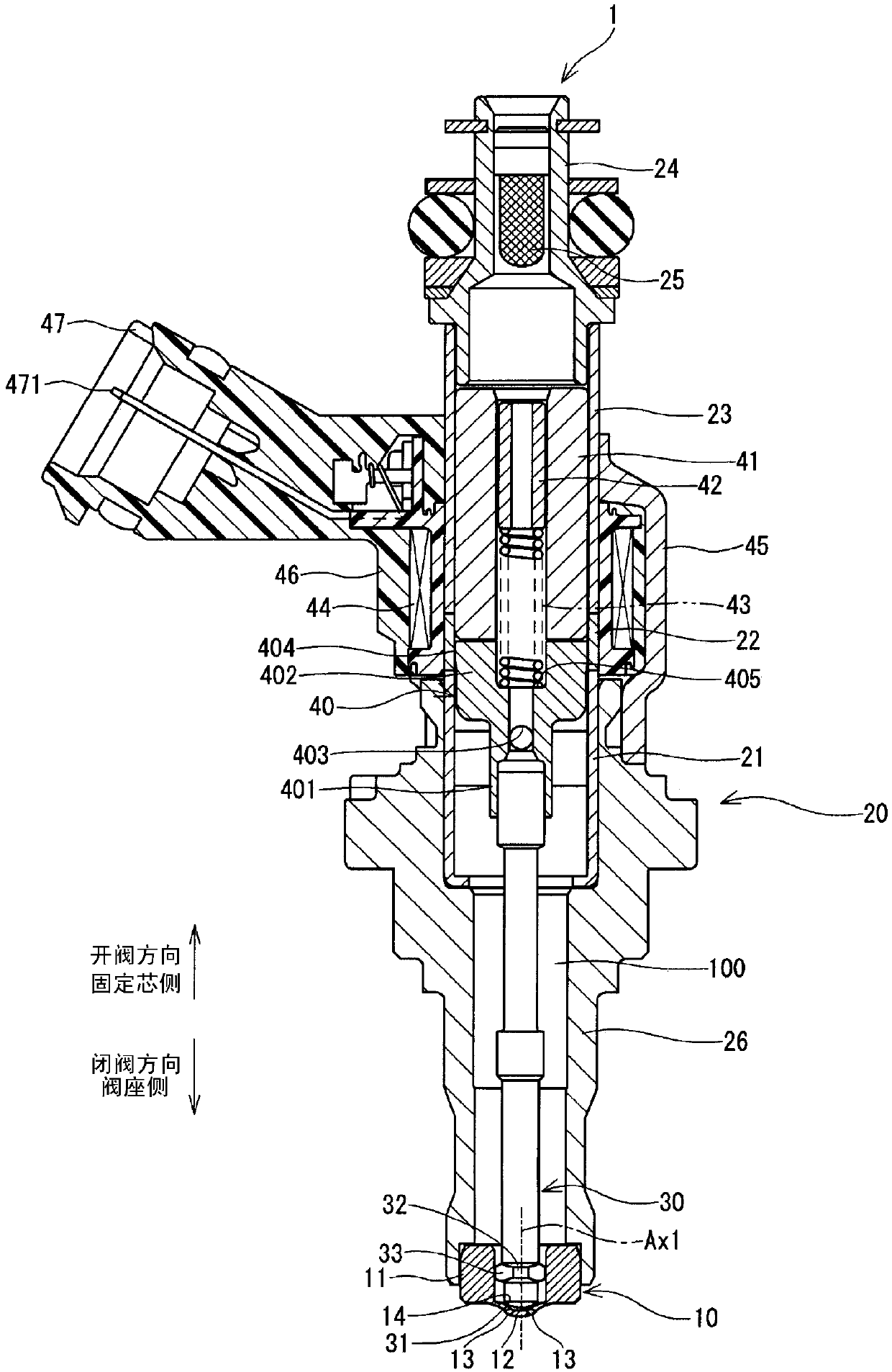
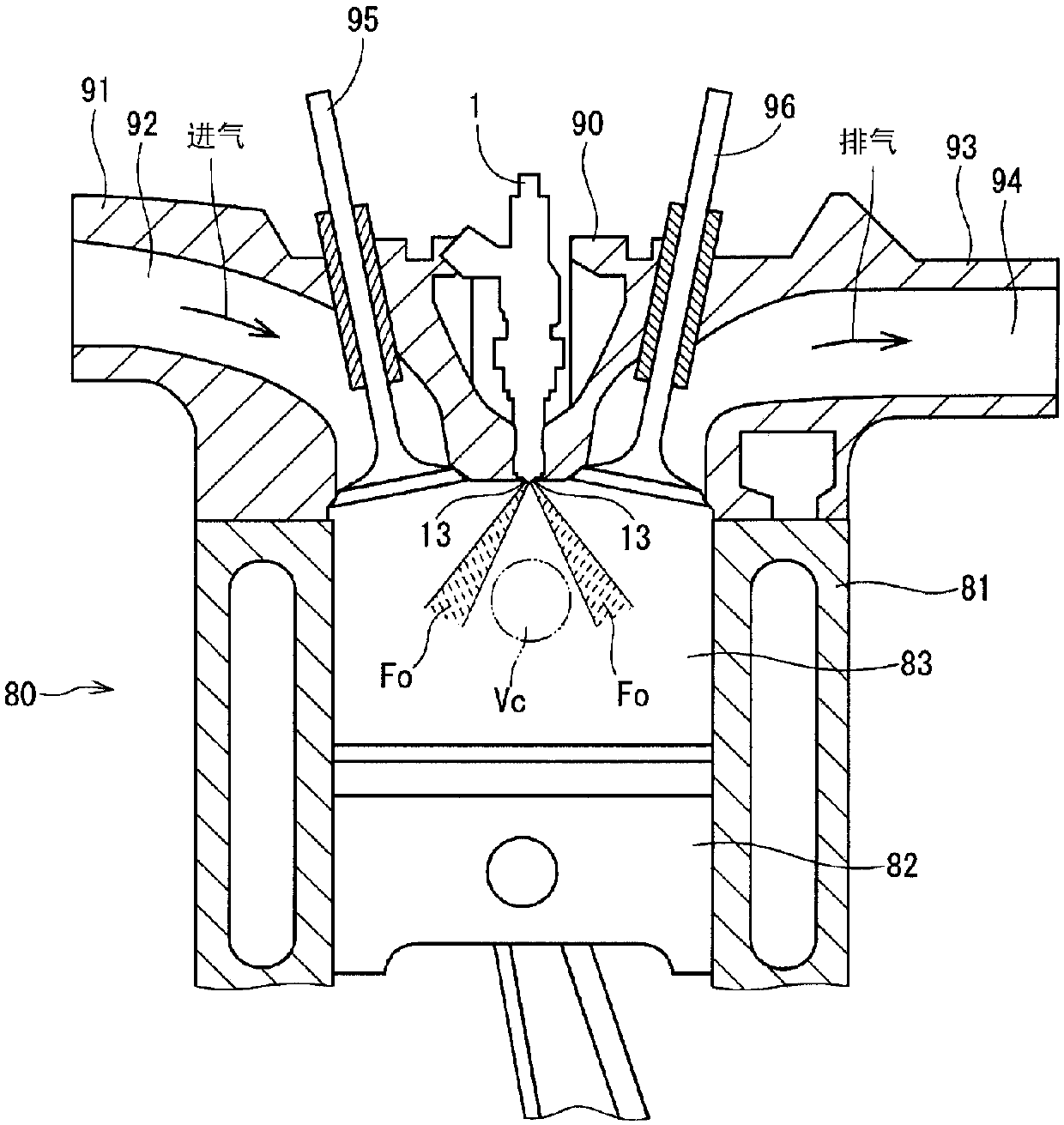
[0039] The fuel injection device according to the first embodiment of the present disclosure is shown in figure 1 middle. The fuel injection device 1 is applied to, for example, a gasoline engine (hereinafter, simply referred to as "engine") 80 as an internal combustion engine, and injects gasoline as fuel to the engine 80 (refer to figure 2 ).
[0040] Such as figure 2 As shown, the engine 80 includes a cylindrical cylinder block 81, a piston 82, a cylinder head 90, an intake valve 95, an exhaust valve 96, and the like. The piston 82 is reciprocally movable inside the cylinder 81 . The cylinder head 90 is provided to close the open end of the cylinder 81 . A combustion chamber 83 is formed between the inner wall of the cylinder block 81 , the wall surface of the cylinder head 90 , and the piston 82 . The volume of the combustion chamber 83 increases and decreases as the piston 82 reciprocates.
[0041] The cylinder head 90 has an intake manifold 91 and an exhaust mani...
no. 2 Embodiment approach
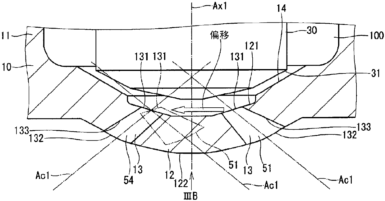
[0114] A part of the fuel injection device according to the second embodiment of the present disclosure is shown in Figure 7A , 7B middle. The arrangement of the injection holes 51, 53, 54, and 56 of the second embodiment is different from that of the first embodiment.
[0115] In the second embodiment, the injection holes 56 , 52 , 54 , 53 , 55 , and 51 are formed sequentially along the circumferential direction of the nozzle bottom 12 (see Figure 7B ). In other words, the injection hole 56 and the injection hole 53, the injection hole 52 and the injection hole 55, and the injection hole 54 and the injection hole 51 are respectively formed in the nozzle bottom 12 so as to sandwich the axis Ax1 of the nozzle cylindrical portion 11 (see Figure 7A , 7B ).
[0116] In addition, when comparing the arrangement of the injection holes 13 in the first embodiment with the arrangement of the injection holes 13 in the second embodiment, the positions of the injection holes 51 and...
no. 3 Embodiment approach
[0123] A part of the fuel injection device according to the third embodiment of the present disclosure is shown in Figure 8A , 8B middle. The arrangement of the injection holes 51, 52, and 56 of the third embodiment is different from that of the first embodiment.
[0124] In the third embodiment, the injection holes 56 , 51 , 53 , 54 , 55 , and 52 are sequentially formed along the circumferential direction of the nozzle bottom 12 (see Figure 8B ). In other words, the injection hole 56 and the injection hole 54, the injection hole 51 and the injection hole 55, and the injection hole 53 and the injection hole 52 are respectively formed in the nozzle bottom 12 so as to sandwich the axis Ax1 of the nozzle cylindrical portion 11 (see Figure 8A , 8B ).
[0125]In addition, when the arrangement of the injection holes 13 of the first embodiment is compared with the arrangement of the injection holes 13 of the second embodiment, the positions of the injection holes 51, 52, and ...
PUM
 Abstract
Description
Claims
Application Information
 - R&D
- Intellectual Property
- Life Sciences
- Materials
- Tech Scout
- Unparalleled Data Quality
- Higher Quality Content
- 60% Fewer Hallucinations
Browse by: Latest US Patents, China's latest patents, Technical Efficacy Thesaurus, Application Domain, Technology Topic, Popular Technical Reports.
© 2025 PatSnap. All rights reserved.Legal|Privacy policy|Modern Slavery Act Transparency Statement|Sitemap|About US| Contact US: help@patsnap.com


