fuel injection device

A fuel injection device, fuel technology, applied in the direction of fuel injection device, charging system, combustion engine, etc., can solve the problems of influence, fuel increase, fuel consumption performance, deterioration, etc.

Active Publication Date: 2019-11-26
DENSO CORP
View PDF2 Cites 0 Cited by
  • Summary
  • Abstract
  • Description
  • Claims
  • Application Information

AI Technical Summary

Problems solved by technology

Therefore, in the fuel injection device of Patent Document 1, there is a concern that the spray of fuel injected from the injection hole is greatly affected by the Coanda effect.
[0008] In addition, in general, the higher the pressure of the injected fuel, the greater the influence of the Coanda effect. Therefore, in the fuel injection device of Patent Document 1, if the injected fuel is pressurized, there is a concern that unburned fuel may be destroyed. Increase or deterioration of fuel consumption performance further becomes significant

Method used


Image

  • fuel injection device
  • fuel injection device
  • fuel injection device

Examples


no. 1 Embodiment approach

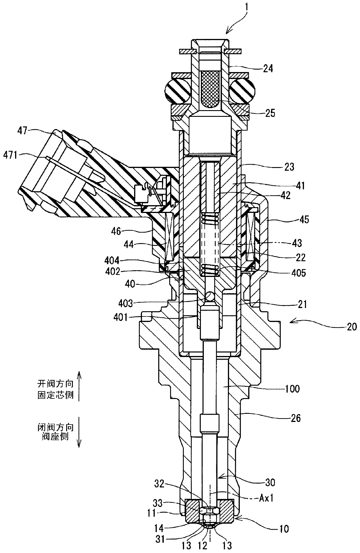
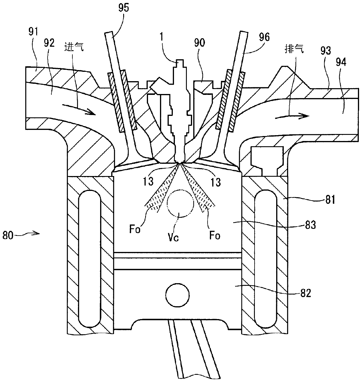
[0039] The fuel injection device according to the first embodiment of the present disclosure is shown in figure 1 middle. The fuel injection device 1 is applied to, for example, a gasoline engine (hereinafter, simply referred to as "engine") 80 as an internal combustion engine, and injects gasoline as fuel to the engine 80 (refer to figure 2 ).

[0040] Such as figure 2 As shown, the engine 80 includes a cylindrical cylinder block 81, a piston 82, a cylinder head 90, an intake valve 95, an exhaust valve 96, and the like. The piston 82 is reciprocally movable inside the cylinder 81 . The cylinder head 90 is provided to close the open end of the cylinder 81 . A combustion chamber 83 is formed between the inner wall of the cylinder block 81 , the wall surface of the cylinder head 90 , and the piston 82 . The volume of the combustion chamber 83 increases and decreases as the piston 82 reciprocates.

[0041] The cylinder head 90 has an intake manifold 91 and an exhaust mani...

no. 2 Embodiment approach

[0114] A part of the fuel injection device according to the second embodiment of the present disclosure is shown in Figure 7A , 7B middle. The arrangement of the injection holes 51, 53, 54, and 56 of the second embodiment is different from that of the first embodiment.

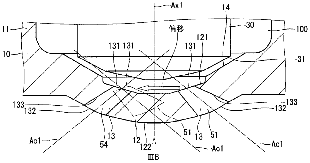
[0115] In the second embodiment, the injection holes 56 , 52 , 54 , 53 , 55 , and 51 are formed sequentially along the circumferential direction of the nozzle bottom 12 (see Figure 7B ). In other words, the injection hole 56 and the injection hole 53, the injection hole 52 and the injection hole 55, and the injection hole 54 and the injection hole 51 are respectively formed in the nozzle bottom 12 so as to sandwich the axis Ax1 of the nozzle cylindrical portion 11 (see Figure 7A , 7B ).

[0116] In addition, when comparing the arrangement of the injection holes 13 in the first embodiment with the arrangement of the injection holes 13 in the second embodiment, the positions of the injection holes 51 and...

no. 3 Embodiment approach

[0123] A part of the fuel injection device according to the third embodiment of the present disclosure is shown in Figure 8A , 8B middle. The arrangement of the injection holes 51, 52, and 56 of the third embodiment is different from that of the first embodiment.

[0124] In the third embodiment, the injection holes 56 , 51 , 53 , 54 , 55 , and 52 are sequentially formed along the circumferential direction of the nozzle bottom 12 (see Figure 8B ). In other words, the injection hole 56 and the injection hole 54, the injection hole 51 and the injection hole 55, and the injection hole 53 and the injection hole 52 are respectively formed in the nozzle bottom 12 so as to sandwich the axis Ax1 of the nozzle cylindrical portion 11 (see Figure 8A , 8B ).

[0125]In addition, when the arrangement of the injection holes 13 of the first embodiment is compared with the arrangement of the injection holes 13 of the second embodiment, the positions of the injection holes 51, 52, and ...


PUM


Abstract

The angle formed by the central axes (Ac1) when the central axes (Ac1) are shifted so as to overlap at the inlet opening (131) in all combinations of the two injection holes (13) is The angle between the two nozzle holes (13) of the combination of the smallest angle between the nozzle holes is set as γamin (deg), and the respective central axes (Ac1 ) on the section taken by the virtual plane of the injection hole (133), that is, the angle formed by the contour of the injection hole inner wall (133), that is, the cone angle is respectively set as θa1, θa2 (deg), and the fuel passage (100) when injecting fuel from the injection hole (13) The average pressure of the fuel is set as P (MPa), then the injection hole (13) is formed to satisfy γamin≥θa1+θa2+0.5×P 0.6 Relationship.

Description

[0001] Cross-reference of related applications [0002] This application is based on Japanese Patent Application No. 2015-146636 for which it applied on July 24, 2015, and uses the description content here. technical field [0003] The present disclosure relates to a fuel injection device for injecting fuel into an internal combustion engine. Background technique [0004] Conventionally, there is known a fuel injection device having a plurality of injection holes whose inner walls are formed in a tapered shape so that the central axis is separated from the inlet opening side toward the outlet opening side. For example, Patent Document 1 describes a fuel injection device in which six injection holes having tapered inner walls are formed. [0005] In the fuel injection device of Patent Document 1, since the diameter of the inner wall of the injection hole is formed to increase toward the outlet opening side, the spray of fuel injected from the injection hole spreads away from...

Claims


Application Information

Patent Timeline
Patent Type & Authority Patents(China)
IPC IPC(8): F02M61/18F02M61/04
CPCF02B23/104F02M61/1806F02M61/1813F02M61/1833F02M61/184Y02T10/12F02M61/04F02M61/10F02M61/18F02M61/1853
Inventor 加藤典嗣
Owner DENSO CORP
Why Eureka
Try Eureka