

fuel injection valve
A fuel injection valve, fuel injection technology, applied in the direction of fuel injection device, charging system, machine/engine, etc., can solve the problem of unconsidered problems, and achieve the effect of high productivity and excellent atomization
- Summary
- Abstract
- Description
- Claims
- Application Information
AI Technical Summary
Problems solved by technology
Method used
Image

Examples
Embodiment 1
[0036] Regarding the first embodiment of the present invention, using figure 1 It will be explained until Fig. 9 .
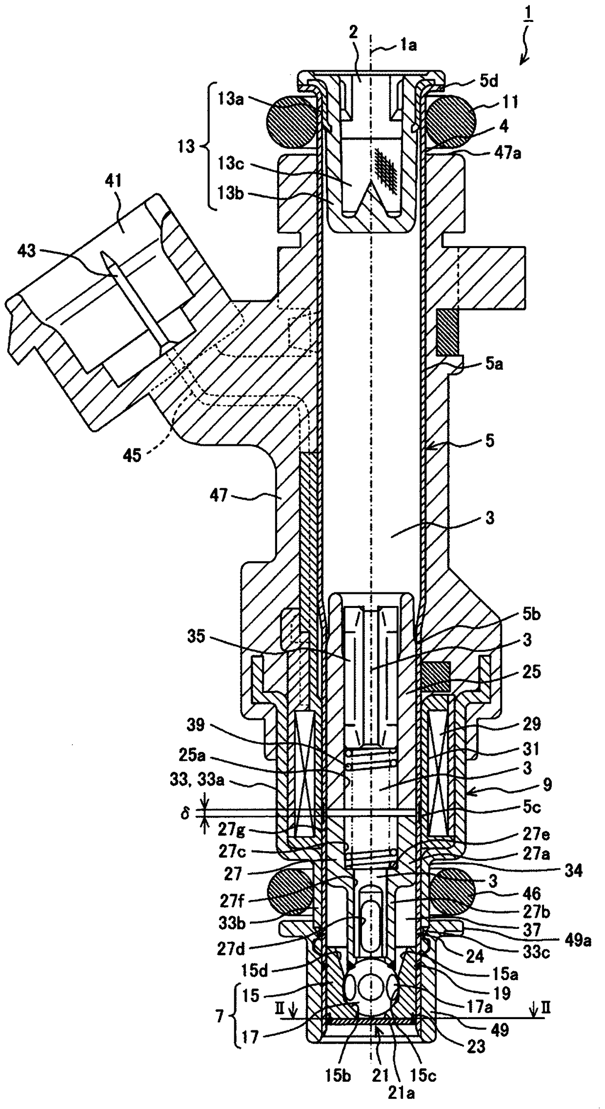
[0037] refer to figure 1 , the overall structure of the fuel injection valve 1 will be described. figure 1 It is a longitudinal sectional view showing a section (longitudinal section) along the central axis 1a of the fuel injection valve 1 . The central axis 1 a coincides with the axis (valve axis) of the movable element 27 integrally formed with the valve body 17 described later, and coincides with the central axis of the cylindrical body 5 described later. In addition, the central axis line 1a also coincides with the axis line of the valve seat 15b described later.
[0038] The fuel injection valve 1 is configured such that the fuel flow path 3 substantially extends along the central axis 1 a inside a cylindrical body 5 made of a metallic material. The cylindrical body 5 is formed into a stepped shape along the direction of the central axis 1 a by using...
Embodiment 2
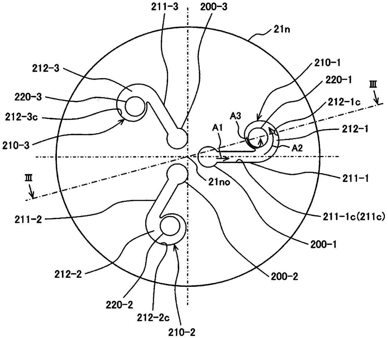
[0127] Below, refer to Figure 12 A second embodiment of the present invention will be described. Figure 12 is the expression from figure 2 The cross-sectional view of the same cross-section of the valve seat member and the nozzle plate is observed in the direction of the III-III arrow. In this example, from Figure 12 The sectional view viewed in the direction of the II-II arrow with figure 2 same. In this case, figure 2 The nozzle plate 21n in the above may be composed of a composite member of the valve seat member 15 and the nozzle plate 21n.
[0128] In the second embodiment, the side surface (side wall surface) 200c of the vertical passage 200 in the first embodiment, the side surface (side wall surface) 211c of the transverse passage 211, and the inner peripheral surface (side wall surface) 212c of the swirl chamber 212 are groove-shaped. It is formed on the front end surface 15t of the valve seat member 15 . A swirl chamber bottom surface 212b inclined with resp...
Embodiment 3
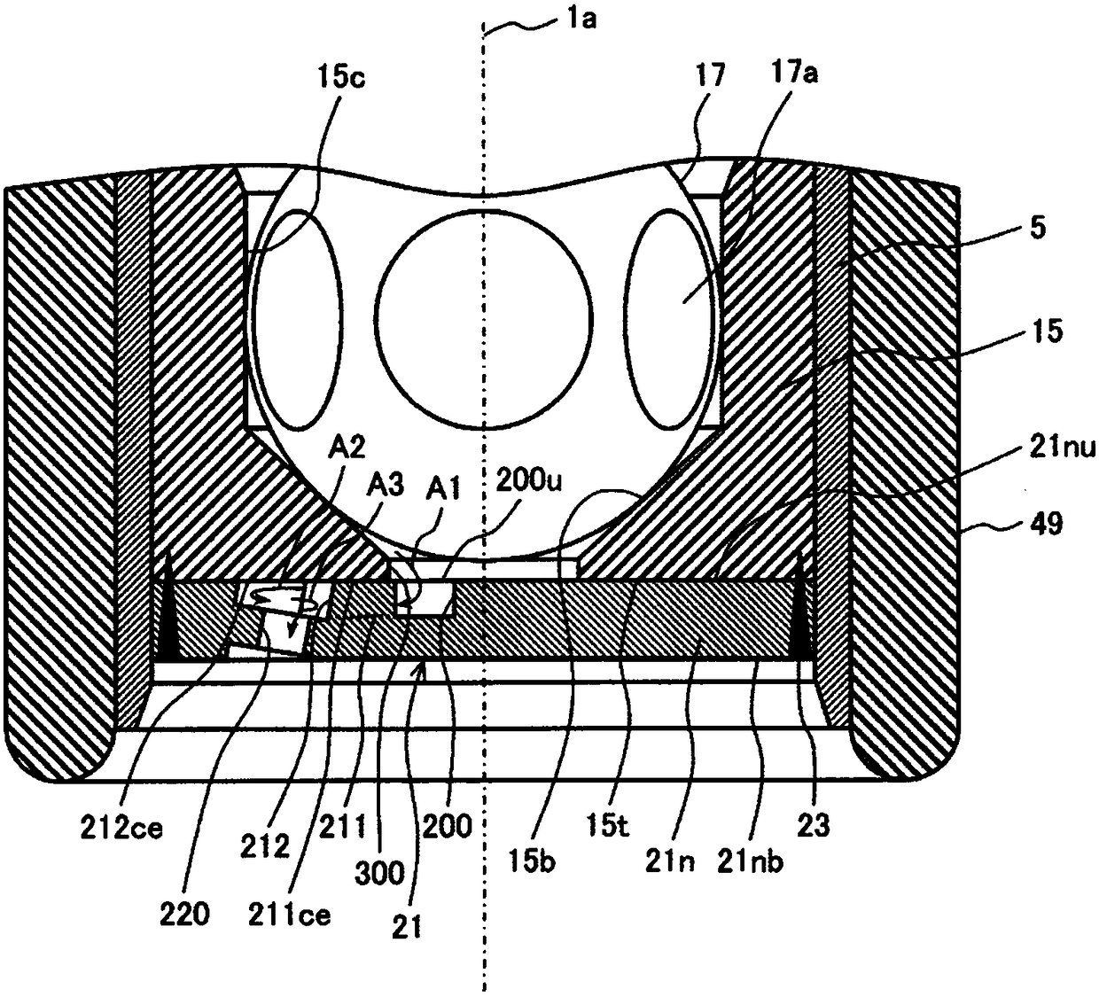
[0131] Below, refer to Figure 13 A third embodiment of the present invention will be described. Figure 13 is the expression from image 3 The sectional view of the same section as the sectional view of the valve seat member and the nozzle plate viewed in the direction of the III-III arrow. The plan view of the side of the upper end surface 21nu of the nozzle plate 21n of this embodiment and figure 2 The top view shown is the same.
[0132] In the third embodiment, the structures of the top surface of the swirl chamber 212 and the top surface of the lateral passage 211 are changed from those of the first embodiment. That is, the top surface 212ce of the swirl chamber 211 and the top surface 211ce of the lateral passage 211 are formed in a convex shape on the front end surface 15t of the valve seat member. The swirl chamber top surface 212ce is inclined similarly to the swirl chamber bottom surface 212b. That is, the inclination direction and inclination angle of the swir...
PUM
 Abstract
Description
Claims
Application Information