Vortex chamber combustion system utilizing umbrella-shaped spray

A technology of combustion system and vortex chamber, which is applied in the direction of combustion engine, internal combustion piston engine, machine/engine, etc., which can solve the problem of increased channel flow loss, heat dissipation loss of vortex chamber wall, poor economy and cold start performance, and heat dissipation loss of vortex chamber wall Large and other problems, to achieve the effect of improved cold start performance, small excess air coefficient, and increased power

Inactive Publication Date: 2012-04-18
DALIAN UNIV OF TECH
View PDF4 Cites 0 Cited by
  • Summary
  • Abstract
  • Description
  • Claims
  • Application Information

AI Technical Summary

Problems solved by technology

[0002] The vortex chamber diesel engine has the advantages of low cost, soft operation, low noise, high reliability and low emission, but its economy and cold start performance are worse than those of the direct injection diesel engine. Large loss, slow heat release in the main combustion chamber
Increasing the vortex intensity of the vortex chamber can improve the formation of the mixture and improve the combustion efficiency, but at the same time it will inevitably increase the flow loss of the channel and the heat dissipation loss of the wall of the vortex chamber, resulting in poor cold start performance and not necessarily increasing the thermal efficiency

Method used


Image

  • Vortex chamber combustion system utilizing umbrella-shaped spray
  • Vortex chamber combustion system utilizing umbrella-shaped spray
  • Vortex chamber combustion system utilizing umbrella-shaped spray

Examples


Embodiment Construction

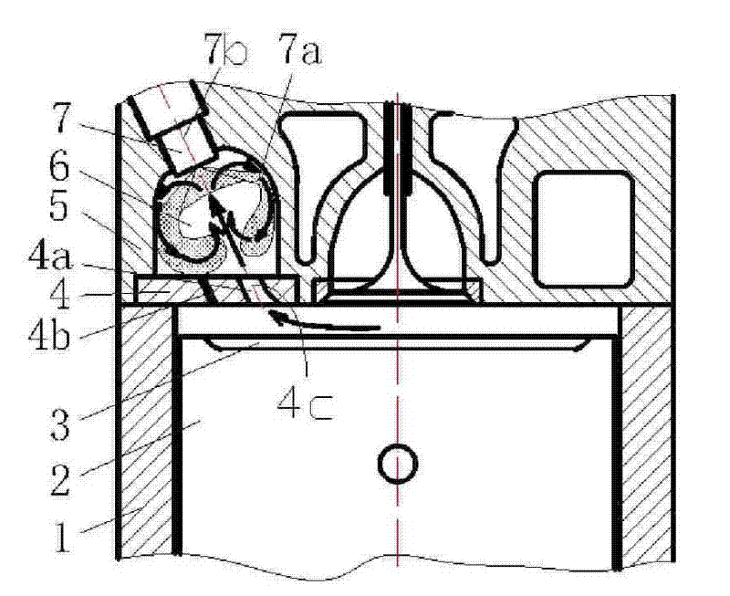
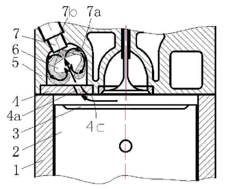
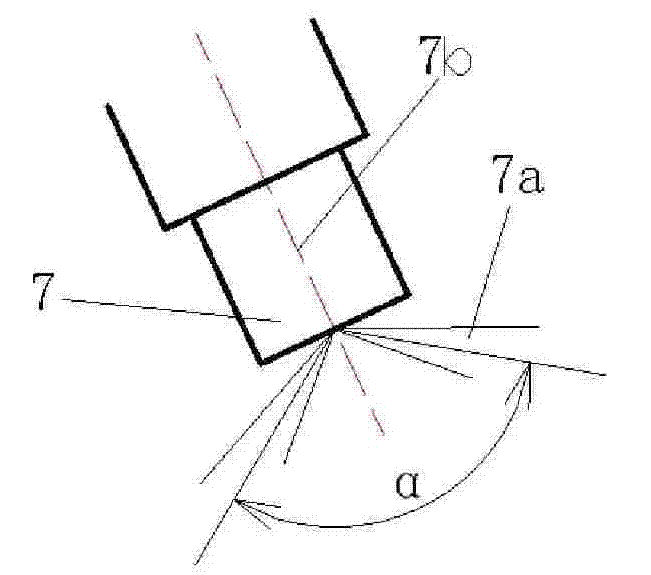
[0014] figure 1 A schematic diagram of a swirl chamber combustion system utilizing an umbrella spray with a start-up hole is shown. The figure mainly shows the main combustion chamber 3, the swirl chamber 6 and the insert 4, and the insert 4 is provided with a main channel 4a and a starting hole 4b connecting the main combustion chamber 3 and the swirl chamber 6. In addition, there is also an umbrella-shaped spray nozzle 7 for spraying umbrella-shaped spray 7a into the swirl chamber 6. The nozzle centerline 7b of the umbrella-shaped spray nozzle 7 overlaps with the channel centerline 4c of the main channel 4a.

[0015] The function of the start-up hole 4b designed on the insert is that during cold start-up, the airflow velocity in the vortex chamber 6 is low, and part of the sprayed oil particles can directly enter the main combustion chamber 3 with relatively high air temperature from the start-up hole 4b. Ignition and combustion in the main combustion chamber 3, or re-enter...


PUM


Abstract

The invention relates to a vortex chamber combustion system utilizing umbrella-shaped spraying, which belongs to the fields of formation and combustion of engine mixing gases. The vortex chamber combustion system utilizing an oil nozzle with an umbrella-shaped spraying has the structural characteristics that the center line of the oil nozzle with an umbrella-shaped spraying way is superposed withthe center line of a main passage so that the air which flows into a vortex chamber from a compression stroke via the main passage turns back along the wall surface of the vortex chamber to form vortex after reaching the vicinity of the head part of the oil nozzle; the direction of the vortex is just along the diffused direction of the umbrella-shaped spraying so as to accelerate oil and gas mixture and improve the combustion. Because the characteristics of short penetrating distance, even circumferential distribution and high granulation of the umbrella-shaped spraying are reasonably utilized, the favorable mixture and combustion can be obtained at lower vortex strength, thereby reducing heat dissipation loss and throttling loss and further improving the heat efficiency of an engine. Experiments on a single-cylinder 195 diesel engine indicate that the power is improved by 10 percent, the oil consumption is reduced by 8 percent, the discharge of NOx is reduced by 10 percent and the discharge of soot is reduced by 20 percent after the vortex chamber combustion system utilizing the oil nozzle with a umbrella-shaped spraying way is adopted.

Description

technical field [0001] The invention relates to a vortex chamber combustion system using an umbrella-shaped spray, belonging to the field of engine mixture gas formation and combustion. Background technique [0002] The vortex chamber diesel engine has the advantages of low cost, soft operation, low noise, high reliability and low emission, but its economy and cold start performance are worse than those of the direct injection diesel engine. The loss is large, and the heat release of the main combustion chamber is slow. Increasing the vortex intensity of the vortex chamber can improve the formation of the mixture and improve the combustion efficiency, but at the same time it will inevitably increase the flow loss of the channel and the heat dissipation loss of the wall of the vortex chamber, resulting in poor cold start performance and not necessarily increasing the thermal efficiency. Therefore, if a good mixture can be obtained at a lower swirl intensity, it will produce ...

Claims


Application Information

Patent Timeline
Patent Type & Authority Patents(China)
IPC IPC(8): F02B23/00
CPCY02T10/125Y02T10/12
Inventor 隆武强冯文奇冷先银盛凯杜宝国陈火雷
Owner DALIAN UNIV OF TECH
Why Eureka
Try Eureka