Bimorph alignment-type multifunctional welding jig

A technology for welding fixtures and double wafers, applied in welding equipment, manufacturing tools, auxiliary devices, etc., can solve problems such as low welding efficiency, difficulty in controlling welding quality, and many processes, and achieve cost reduction, reduction of scrap rate, and simplified Process effect

Active Publication Date: 2015-12-30
广东卓瑞科技教育股份有限公司
View PDF7 Cites 0 Cited by
  • Summary
  • Abstract
  • Description
  • Claims
  • Application Information

AI Technical Summary

Problems solved by technology

At present, due to the lack of special welding fixtures, the three parts can only be welded separately by hand, the welding efficiency is low, and the welding quality is difficult to control; moreover, due to the multi-bending structure of the support plate 3, it needs to be calibrated and tested after processing. , currently mainly use independent detection device, its process is more

Method used


Image

  • Bimorph alignment-type multifunctional welding jig
  • Bimorph alignment-type multifunctional welding jig
  • Bimorph alignment-type multifunctional welding jig

Examples


Embodiment Construction

[0024] The specific embodiments of the present invention will be further described below in conjunction with the accompanying drawings.

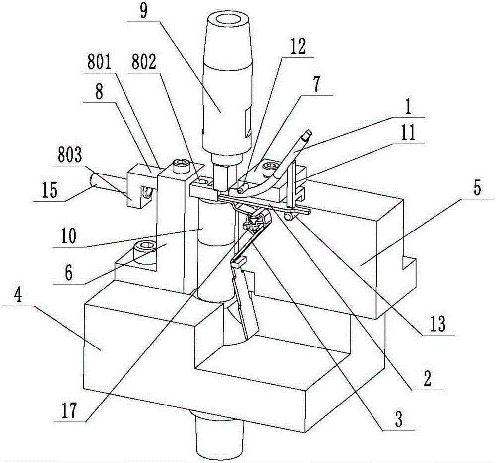
[0025] Such as Figure 7 As shown, the dual-chip calibration multifunctional welding fixture of this embodiment is used for welding between the double chip 2, the copper wire 1 and the support plate 3. The copper wire 1 is curved and its welding end is a square tube end. 101, the support plate 3 is a multi-bending structure, which has an upper horizontal plate welding end 301, a middle middle bending part 302 and a lower lower bending part 303, the middle bending part 302 and the lower bending part 303 The direction of deflection is opposite.

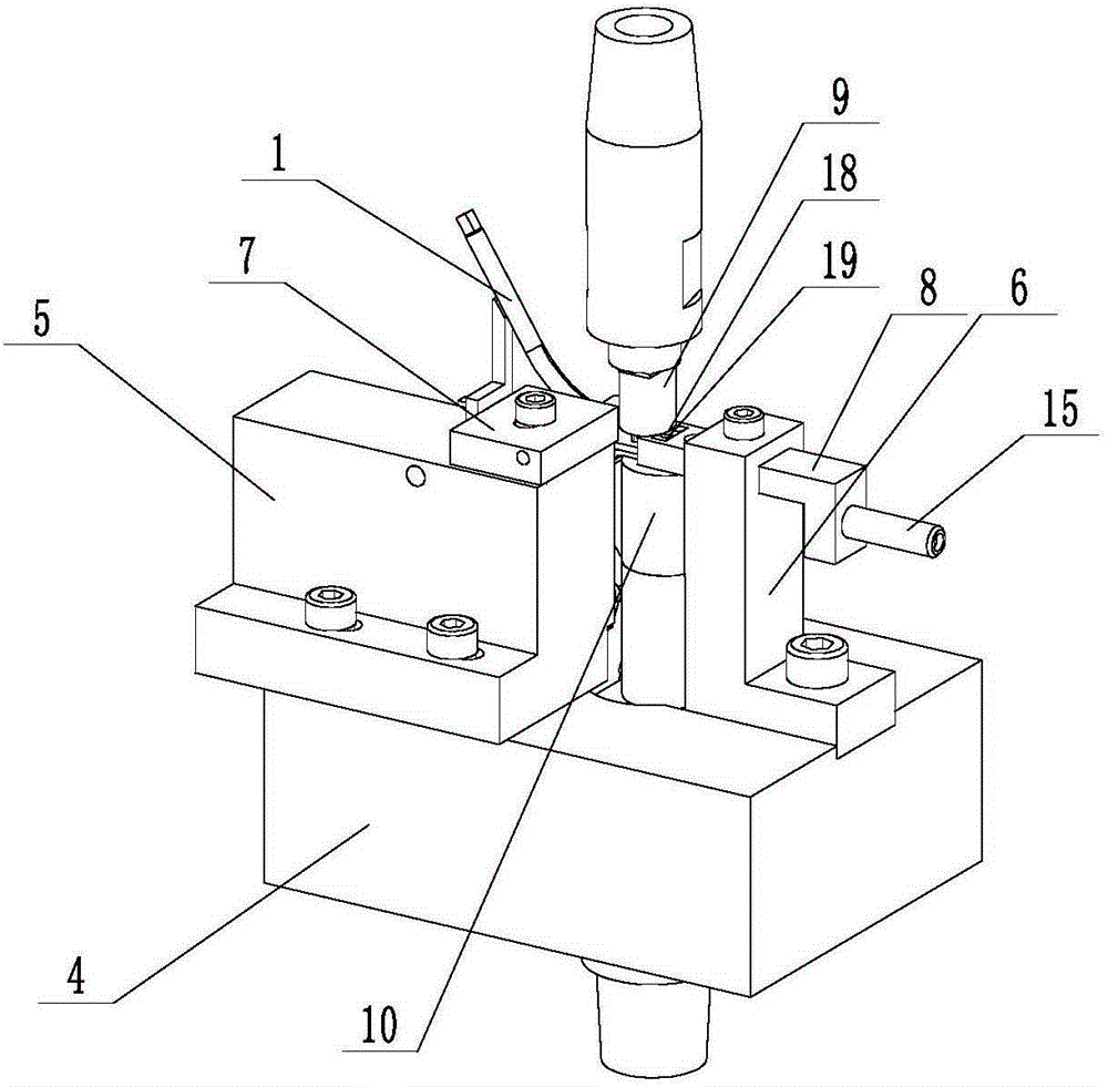
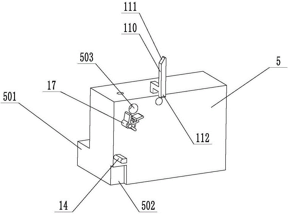
[0026] Such as figure 1 , figure 2 , image 3 and Figure 4 As shown, the welding jig includes a welding seat 4, the center of the welding seat 4 is equipped with a lower fixed electrode 10, and an upper movable electrode 9 is arranged above the lower fixed electrode 10, and is installed on the ...


PUM


Abstract

The invention relates to a bimorph alignment-type multifunctional welding jig. The bimorph alignment-type multifunctional welding jig comprises a welding seat; a lower fixing electrode is mounted at the center of the welding seat; an upper movable electrode is arranged above the lower fixing electrode; a first fixing seat and a second fixing seat are mounted on the welding seat at the two sides of the lower fixing electrode; a positioning block and a positioning frame are mounted on the upper end surface of the first fixing seat; an upper blocking pillar is mounted on the side surface of the positioning block; a lower blocking pillar is arranged on the side surface of the first fixing seat, and is positioned below and staggered with the upper blocking pillar; a bimorph is mounted between the upper blocking pillar and the lower blocking pillar; a square pipe end of a copper wire is mounted between the bimorph and the upper blocking pillar, and the other end of the copper wire is propped against the upper end of the positioning frame; a positioning pillar for limiting a support plate and a positioning alignment frame are arranged on the side surface of the first fixing seat; an end part limiting frame is mounted on the second fixing seat; the end part limiting frame is positioned on the upper end surface of the lower fixing electrode, and propped against the ends surfaces of the bimorph, the cross plate welding end, and the square pipe end; a photoelectric counter and a photoelectric induction switch are mounted on the end part limiting frame.

Description

technical field [0001] The invention relates to the field of welding technology, in particular to a welding jig for double wafers. Background technique [0002] Such as Figure 7 As shown, the workpieces to be welded include a double chip 2, a copper wire 1 and a support plate 3, the copper wire 1 is curved, and its welding end is a square pipe end 101, and the support plate 3 is a multi-bend structure with an upper horizontal The welding end 301 of the plate, the middle bending part 302 in the middle and the lower bending part 303 in the lower part, the bending directions of the middle bending part 302 and the lower bending part 303 are opposite. At present, due to the lack of special welding fixtures, the three parts can only be welded separately by hand, the welding efficiency is low, and the welding quality is difficult to control; moreover, due to the multi-bending structure of the support plate 3, it needs to be calibrated and tested after processing. , At present, an...

Claims


Application Information

Patent Timeline
Patent Type & Authority Applications(China)
IPC IPC(8): B23K3/08
CPCB23K3/087B23K2101/40
Inventor 袁源远
Owner 广东卓瑞科技教育股份有限公司
Why Eureka
Try Eureka