Rotor punching plate, motor rotor and motor

A technology for rotor punching and motor rotors, which is applied to the rotating parts of the magnetic circuit, the shape/style/structure of the magnetic circuit, etc., and can solve the problems of insignificant skin effect, large slot leakage reactance, and low air gap magnetic density. , to achieve the effect of increasing skin effect, improving performance and uniform magnetic density

Inactive Publication Date: 2015-12-30
GREE ELECTRIC APPLIANCES INC +1
View PDF5 Cites 0 Cited by
  • Summary
  • Abstract
  • Description
  • Claims
  • Application Information

AI Technical Summary

Problems solved by technology

The pear-shaped groove has the advantages of high groove area utilization, long die life, and easy mold manufacturing. However, because the groove is wide and shallow, the skin effect is not obvious, the leakage resistance of the groove is large, the rotor teeth are small, and the teeth magnetic The density is supersaturated, and there are also disadvantages such as low efficiency and low air gap magnetic density.

Method used


Image

  • Rotor punching plate, motor rotor and motor
  • Rotor punching plate, motor rotor and motor

Examples


Embodiment Construction

[0018] The core of the present invention is to provide a rotor punch to increase the skin effect of the motor, while ensuring uniform magnetic density at the tooth portion and good operating performance;

[0019] Another core of the present invention is to provide a motor rotor and a motor.

[0020] Hereinafter, an embodiment will be described with reference to the drawings. In addition, the examples shown below do not limit the content of the invention described in the claims in any way. In addition, all the contents of the configurations shown in the following embodiments are not limited to be essential to the solutions of the invention described in the claims.

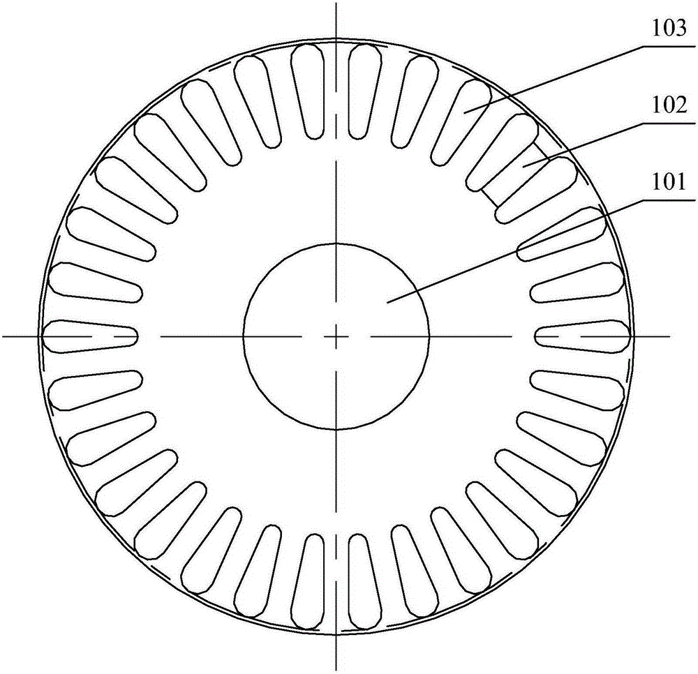
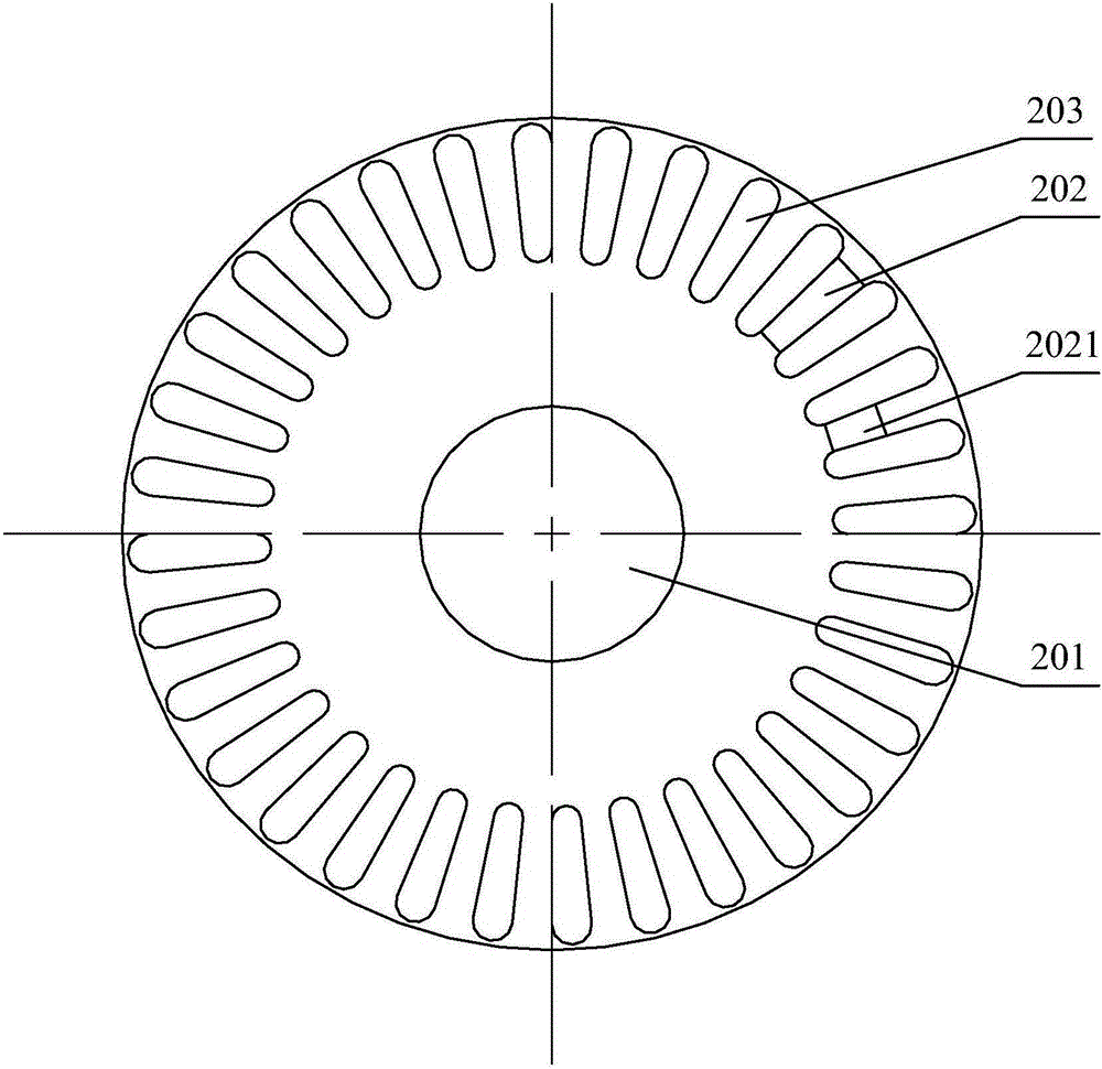
[0021] see figure 2 , figure 2 It is a schematic structural diagram of the rotor punch provided by the embodiment of the present invention.

[0022] The rotor stamping provided by the embodiment of the present invention includes a rotor stamping body, the periphery of the rotor stamping body is provided with t...


PUM


Abstract

The embodiment of the invention discloses a rotor punching plate which comprises a rotor punching plate body, wherein toothed slots used for winding a rotor coil is formed in the periphery of the rotor punching plate body; a rotor tooth part is formed between every two adjacent toothed slots; each rotor tooth part is a trapezoid tooth; the end, away from the circle center of the rotor punching plate body, of each rotor tooth part is wider than the other end. The rotor punching plate has the advantages of parallel slots and parallel teeth, the starting current of a motor can be reduced, the starting performance is improved, the skin effect of the motor is enhanced, the added loss of the motor is reduced, and the performance of the motor is integrally improved; besides, the slots are narrow and deep, the leakage reactance at slot openings is less, and the current is greater, so that the skin effect of the current is achieved, and the starting torque is increased. The invention also discloses a motor rotor and a motor.

Description

technical field [0001] The invention relates to the technical field of motors, and more specifically, to a rotor punch, a motor rotor and a motor. Background technique [0002] The motor is composed of a rotor and a stator, and the rotor is formed by laminating the rotor punches. Such as figure 1 As shown, the rotor stamping includes a rotor stamping body, a rotor inner hole 101 is opened in the center of the rotor stamping body, and tooth slots 103 for winding the rotor coil are opened around the periphery, and rotor teeth are formed between two adjacent tooth slots 103 102. [0003] At present, all the existing rotor punches adopt the design of parallel teeth + pear-shaped grooves, that is, the tooth grooves 103 are pear-shaped structures, and the two sides of the rotor tooth portion 102 are parallel structures. The pear-shaped groove has the advantages of high groove area utilization, long die life, and easy mold manufacturing. However, because the groove is wide and s...

Claims


Application Information

Patent Timeline
Patent Type & Authority Applications(China)
IPC IPC(8): H02K1/24
Inventor 陈胜旭范少稳
Owner GREE ELECTRIC APPLIANCES INC
Why Eureka
Try Eureka