Battery box device

A battery box and battery technology, applied in secondary batteries, battery pack components, circuits, etc., can solve the problems of power consumption, large size, power failure, etc., and achieve no misoperation, good product appearance, and economical The effect of electricity

Active Publication Date: 2016-01-06
上海长巍电池系统科技有限公司
View PDF5 Cites 0 Cited by
  • Summary
  • Abstract
  • Description
  • Claims
  • Application Information

AI Technical Summary

Problems solved by technology

[0010] In the prior art, for a secondary battery equipped with a management circuit, the output voltage cannot be cut off immediately; or although a switch can be used to cut off the output voltage on the wiring post immediately, many other problems have arisen: 1. High-current switches are required, which are costly and bulky; 2. In normal use, users are likely to accidentally touch the switch, resulting in accidental power outages; 3. The aesthetics of the battery box is reduced, and the appearance is not concise and smooth; 4. .After the switch is cut off, although there is no voltage on the wiring pile, the system does not enter the dormant state, and the control circuit itself continues to consume electric energy according to the power of the normal working state
Regardless of the first case or the second case, as long as the battery does not enter the sleep state, its control circuit will continue to seriously consume the limited power of the battery

Method used


Image

  • Battery box device
  • Battery box device
  • Battery box device

Examples


Embodiment 1

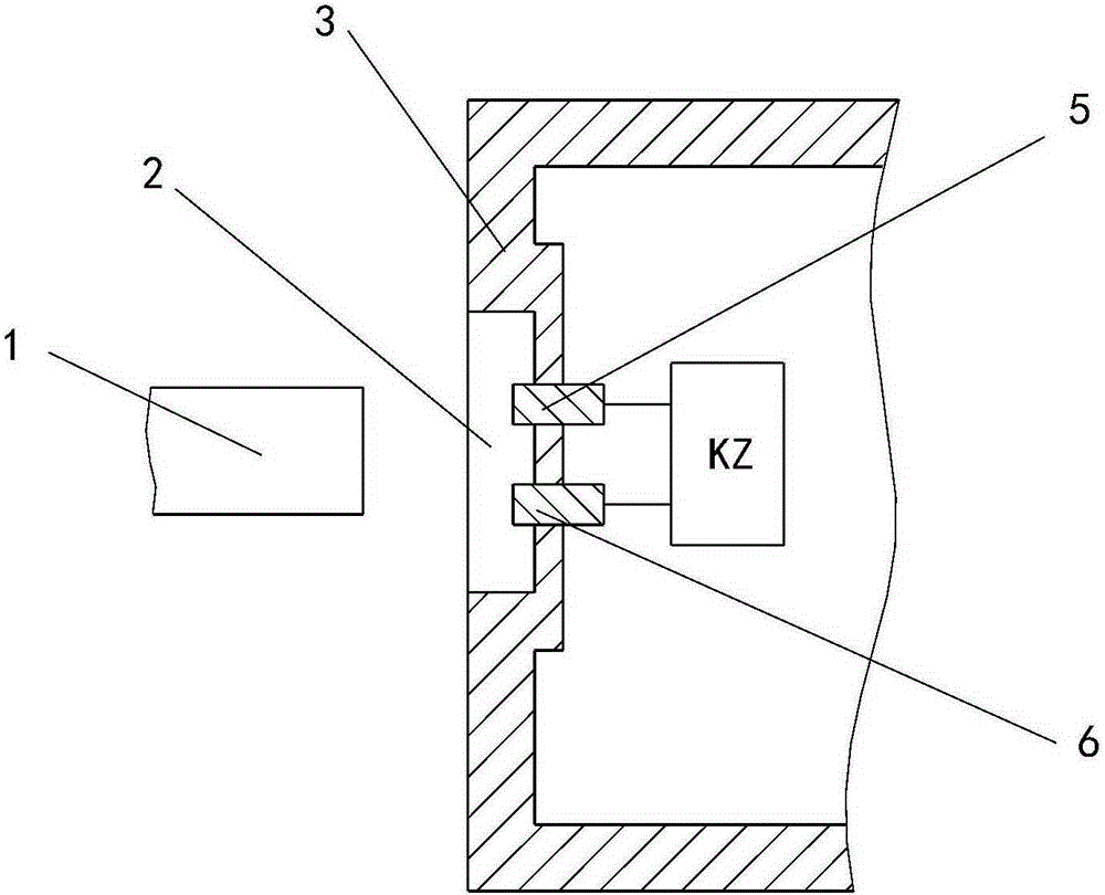
[0141] to combine Figure 26 with Figure 27 Be explained. Figure 26 It is the schematic diagram of the inventive device in the first embodiment; Figure 27 yes Figure 26 top view.

[0142] Explanation of symbols in the figure: 2. Working window; 3. Box body; 3a. Box cover; 3b. Box body; 5-6. Metal body; 6-6. Metal body; 10. Printed circuit board; DD1. Single battery; DD2. Single battery; DD3. Single battery; DD4. Single battery.

[0143] As shown in these two figures, the inventive device of this embodiment includes: a box body, a circuit, and a battery arranged in the box body.

[0144] The box body includes a box cover and a box body; the box cover includes four side panels and a cover plate; the box body includes four side surfaces and a bottom surface; a pair of wiring posts are arranged on the cover plate.

[0145] The batteries in the case are four single cells.

[0146] The dormant operation window is set on the side panel of the box cover; the metal body is a...

Embodiment 2

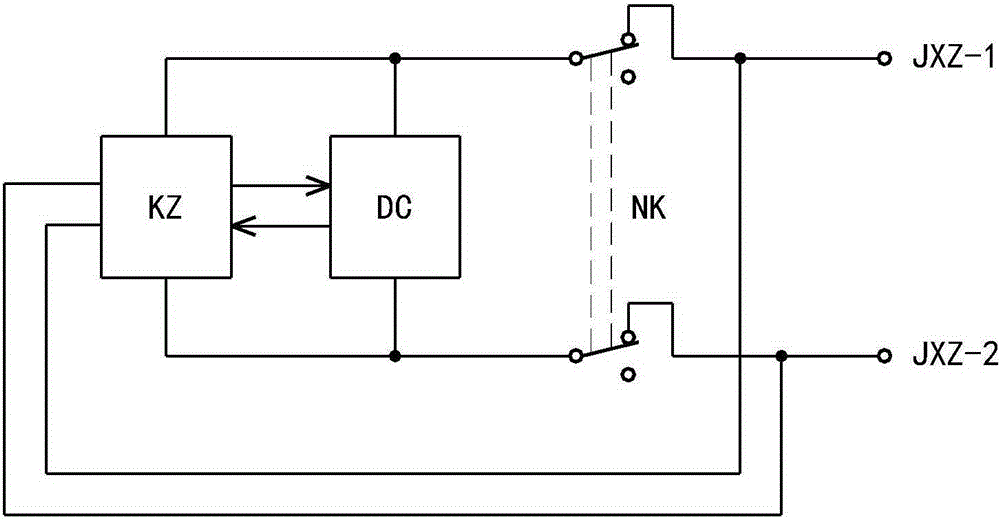
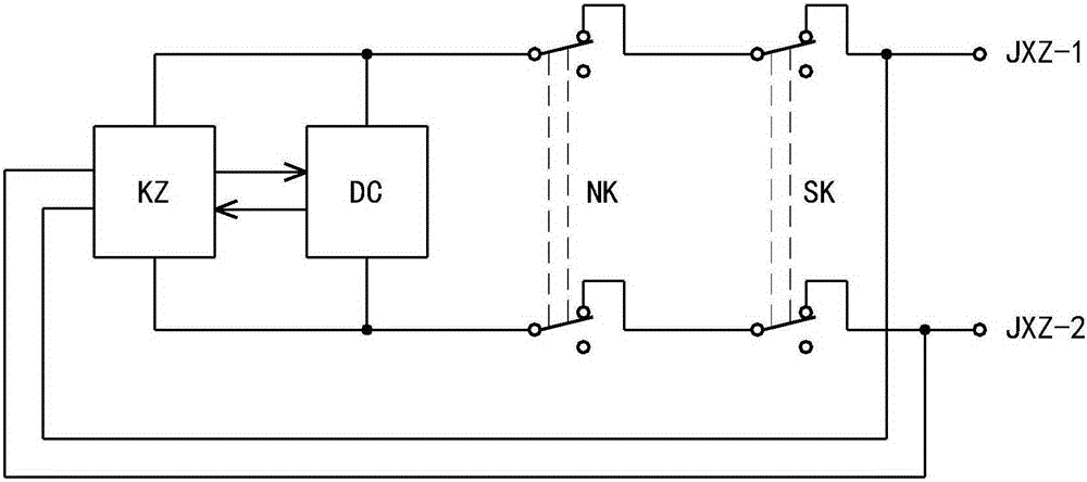
[0148] to combine Figure 28 to Figure 31 Be explained. Figure 28 It is one of the circuit diagrams in the second embodiment; Figure 29 It is the second of the circuit diagram in the second embodiment; Figure 30 It is the third of the circuit diagram in the second embodiment; Figure 31 It is the fourth of the circuit diagram in the second embodiment.

[0149] Explanation of symbols in the figure: 5-7. Metal body; 5-8. Metal body; 5-9. Metal body; 5-10. Metal body; 6-7. Metal body; 6-8. Metal body; 6- 9. Metal body; 6-10. Metal body; CY1. Delay capacitance; CY1. Delay capacitance; DLGJ. Shorting tool; KZ. Control circuit; RX1. Resistance; RX2. Resistance; RX3. Resistance; RX4. Resistance; RX5 .Resistance; RX6.Resistance; RX7.Resistance; V+.Positive pole of DC power supply.

[0150] In the dormant operation window, the staff uses a short-circuit tool to short-circuit two metal bodies. After short-circuiting, there are two detailed options for subsequent operation, and ...

Embodiment 3

[0160] to combine Figure 32 , Figure 33 , Figure 34 with Figure 35 Be explained.

[0161] Figure 32 with Figure 33 The label description in: CK. sleep operation window; PACK+. positive pole of the device; PACK-. negative pole of the device; Wakeup. wake-up circuit; Sleep2. invented sleep circuit; Switch. internal switch; Battery. battery; MCU. MCU pin; V. MCU pin; W. MCU pin; X. MCU pin; ZD1. Regulator tube; ZD2. Regulator tube; ZD3. Regulator tube; ZW. DC regulated power supply; WS. DC Voltage regulator output terminal; R1. resistance; R2. resistance; R3. resistance; R4. resistance; Q. triode; Switch. internal switch.

[0162] Figure 32 is a circuit diagram of a prior art battery box device, the type of battery is a lithium battery; Figure 32 In the device, its control circuit has the following four control functions:

[0163] 1. When charging, the voltage is not allowed to be too high, that is, when the voltage is charged to a certain value, the charging wil...


PUM


Abstract

The invention relates to the technical field of a chemical battery, and discloses a battery box device. In order to solve the problem that the battery box device in the prior art cannot instantaneously enter a dormant state, the technical scheme proposes the battery box device comprising a box, a circuit and more than one battery arranged in the box, wherein the circuit comprises a connection circuit and a control circuit, the battery box device comprises two metal bodies and a short-connected circuit, windows for dormant operation are formed in the box, the ends of the metal bodies or the metal bodies are arranged at the dormant operation windows, and the metal bodies are electrically connected with the control circuit. The battery box device has the advantages that the battery box device can instantaneously enter the dormant state, and the safety during storage and transportation is ensured.

Description

technical field [0001] The invention relates to the technical field of chemical batteries, in particular to a battery box device; the invention is especially applicable to secondary batteries equipped with management circuits. Background technique [0002] A secondary battery can also be called a battery, a storage battery, or an energy storage battery. After the secondary battery is discharged, the internal active material can be regenerated by charging, and the electrical energy is stored as chemical energy; when it needs to be discharged, the chemical energy is converted into electrical energy again. [0003] From the perspective of management, secondary batteries can be divided into two categories. The first category of secondary batteries, such as lithium batteries, must be equipped with management circuits, otherwise they cannot be used normally and safely; the second category of secondary batteries, A typical example is a lead-acid battery, which generally does not n...

Claims


Application Information

Patent Timeline
Patent Type & Authority Applications(China)
IPC IPC(8): H01M10/46H01M10/48H01M2/20H01M50/503
CPCH01M10/46H01M10/482H01M50/50Y02E60/10
Inventor 杨巍
Owner 上海长巍电池系统科技有限公司
Why Eureka
Try Eureka