Wire-arranging method for motor stator winding

A motor stator and wire management technology, which is applied in the direction of electric components, manufacturing motor generators, electrical components, etc., can solve the problems of hidden dangers in motor quality, damage to winding wires, and low production efficiency, so as to improve wire management efficiency and avoid damage Effect

Active Publication Date: 2016-01-06
ZHUHAI KAIBANG MOTOR MFR +1
5 Cites 1 Cited by

AI-Extracted Technical Summary

Problems solved by technology

[0004] It can be seen that at present, in order to avoid the contact between the main bridge wire and the auxiliary winding, it is necessary to cut the tape with a blade, pick out the bridge wire with a bamboo stick, and finally fix the bridge wire from the end face to the outer sur...

Method used

In order to further optimize the scheme, the main bridge line and the auxiliary bridge line in the above-mentioned embodiment are respectively positioned at the relative two ends of the stator core, thereby further reducing the probability of the main bridge line and the auxiliary bridge line contacting, Ensure reliable insulation between primary and secondary windings and improve the quality of the stator.
[0031] After the main bridge line is fixed, it is convenient to carry out the subsequent manufacturing process, effectively a...

Abstract

The invention relates to a wire-arranging method for a motor stator winding. The wire-arranging method includes steps: the winding of a primary winding: during the winding of the primary winding, a main over-bridge line passes for a predetermined length along the excircle surface of a stator core and then enters a tooth portion of the stator core for the winding of the next primary winding so that a first filling gap is reserved between the main over-bridge line and a secondary winding; and the insulation of primary and secondary windings: the main over-bridge line is arranged at an end part of the stator core, and the first filling gap is filled with an insulation part so that the main over-bridge line is insulated from the secondary winding. According to the wire-arranging method, the wire-arranging efficiency of the stator winding is greatly improved, tools such as blades and bamboo sticks are not needed, the main over-bridge line does not need to be selected, and the condition of the damage to stator winding coils is effectively avoided.

Application Domain

Technology Topic

Image

  • Wire-arranging method for motor stator winding

Examples

  • Experimental program(1)

Example Embodiment

[0022] The core of the present invention is to provide a method for arranging wires of motor stator windings, so as to avoid damage to the stator windings and effectively improve the wire arranging efficiency of the stator windings.
[0023] In order to enable those skilled in the art to better understand the solution of the present invention, the present invention will be further described in detail below in conjunction with the accompanying drawings and specific embodiments.
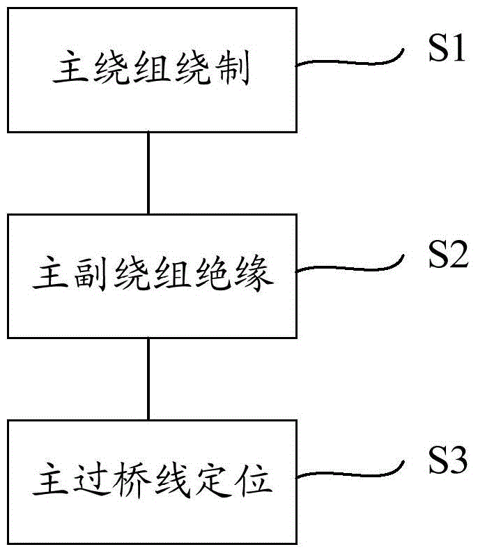
[0024] Please refer to figure 1 , figure 1 It is a flowchart of a method for arranging wires of a motor stator winding disclosed in an embodiment of the present invention.
[0025] In the wiring method of the motor stator winding disclosed in this embodiment, the motor stator includes a stator core, a plurality of main windings and a plurality of auxiliary windings wound on the stator core at intervals, and the adjacent two main windings The windings are connected through the main bridge wire, and the adjacent two secondary windings are connected through the auxiliary bridge wire, and the wiring method includes steps:
[0026] S1) Winding of the main winding. During the winding process of the main winding, the main bridge line first passes through the predetermined length along the outer circular surface of the stator core, and then the main bridge line enters the teeth of the stator core to wind Make a main winding so that the first filler gap is reserved between the main bridge wire and the auxiliary winding.
[0027] S2) Insulate the main and auxiliary windings, arrange the main bridge wires to the end of the stator core, and fill the first filler gap with insulators to insulate the main bridge wires and the auxiliary windings.
[0028] In this embodiment, since the main bridge line passes through the outer circle of the stator for a predetermined length before re-entering the teeth of the stator core to wind the next winding when the main winding is wound, the main bridge line Compared with other coils, the winding is looser, and the main bridge line can be easily found during the line arrangement process, and the main bridge line can be easily arranged at the end of the fixed iron core, and then the main bridge line Insulators are filled between the secondary winding and the main bridge wire to achieve insulation between the secondary winding. This greatly improves the wire management efficiency of the stator winding. At the same time, because this method does not require tools such as blades and bamboo sticks, and does not need to pick out the main bridge wire, it effectively avoids damage to the stator winding coils.
[0029] In order to further optimize the technical solutions in the above embodiments and avoid insulation failure between the main bridge wire and the secondary winding, steps are added in this embodiment:
[0030] S3) Positioning of the main bridge line, using insulating tape to fix the main bridge line and insulating parts at the end of the stator core.
[0031] After the main bridge wire is fixed, the subsequent manufacturing process can be facilitated, and the insulation failure of the main and auxiliary windings of the motor stator can be effectively avoided during the process flow.
[0032] In addition, the present invention also provides another embodiment. In this embodiment, in addition to simplifying the wiring steps of the main bridge line, the wiring steps of the auxiliary bridge line are also simplified. For simplification, on the basis of the foregoing embodiments, this embodiment also includes:
[0033] Secondary winding winding, when winding the secondary winding, the secondary bridge line first passes through the predetermined length along the outer circular surface of the stator core, and then enters the teeth of the stator core to wind the next secondary winding, so that A second filler gap is reserved between the auxiliary bridge wire and the main winding;
[0034] Insulation of main and auxiliary windings: arrange the auxiliary bridge wires to the end of the stator core, and fill insulators in the second filler gap to insulate the auxiliary bridge wires from the main winding.
[0035] Those skilled in the art can easily understand that the technical solution provided in this embodiment can further improve the wire management efficiency of the stator winding, and does not require tools such as blades and bamboo sticks, and does not need to pick out the secondary bridge wires, thus further effectively avoiding The condition of causing damage to the stator winding coils occurs.
[0036] Certainly, in the above-mentioned embodiment, a step can also be added: positioning the auxiliary bridge wire, and fixing the auxiliary bridge wire and the insulating piece to the end of the stator core with insulating tape. This can facilitate the subsequent manufacturing process and effectively prevent the insulation failure of the main and auxiliary windings of the motor stator during the process flow.
[0037] In order to further optimize the solution, the main bridge wire and the auxiliary bridge wire in the above embodiment are respectively positioned at opposite ends of the stator core, thereby further reducing the probability of contact between the main bridge wire and the auxiliary bridge wire and ensuring that the main winding Reliable insulation between the winding and the secondary winding improves the quality of the stator.
[0038] The main bridge line and the auxiliary bridge line pass through the predetermined length along the outer surface of the stator core to form the first filling gap and the second filling gap. If the predetermined length is too large, the winding will appear loose, and if it is too small, it will not Put in the insulation, so in the cable management method disclosed in the present invention, the predetermined length is preferably 3mm-5mm.
[0039] It should be understood that the type of the insulator will not be limited, as long as the reliable insulation between the main and secondary windings can be guaranteed. In the present invention, it is preferred to use paper sheets with low cost and easy availability as the insulator. The job number can also be printed on the paper, so that the manufacturer can track and control the various processes of stator production.
[0040] The motor stator winding wiring method provided by the present invention has been introduced in detail above. In this paper, specific examples are used to illustrate the principle and implementation of the present invention, and the descriptions of the above embodiments are only used to help understand the method and core idea of ​​the present invention. It should be pointed out that for those skilled in the art, without departing from the principles of the present invention, some improvements and modifications can be made to the present invention, and these improvements and modifications also fall within the protection scope of the claims of the present invention.

PUM

PropertyMeasurementUnit
Length3.0 ~ 5.0mm
tensileMPa
Particle sizePa
strength10

Description & Claims & Application Information

We can also present the details of the Description, Claims and Application information to help users get a comprehensive understanding of the technical details of the patent, such as background art, summary of invention, brief description of drawings, description of embodiments, and other original content. On the other hand, users can also determine the specific scope of protection of the technology through the list of claims; as well as understand the changes in the life cycle of the technology with the presentation of the patent timeline. Login to view more.

Similar technology patents

Rubber-plastic mining air duct with reflective effect

InactiveCN107246278AEasy to walkAvoid causing harmTunnel/mines ventillationEngineeringTextile
Owner:阜宁县曙光合成革有限公司

Building fire-fighting robot

PendingCN111228701AAvoid causing harmFire rescueWater pipeWater storage tank
Owner:IANGSU COLLEGE OF ENG & TECH

Electric wire arranging device and method

ActiveCN105293193AImprove cable management efficiencySimple structureSlide plateElectrical wiring
Owner:襄阳中车电机技术有限公司

Biosafety cabinet with external scanning equipment

PendingCN111957357AAvoid causing harmImprove operational convenienceEnclosures/chambersSurveillance cameraStructural engineering
Owner:上海上净净化设备有限公司

Classification and recommendation of technical efficacy words

  • Improve cable management efficiency
  • Avoid causing harm

Electric wire arranging device and method

ActiveCN105293193AImprove cable management efficiencySimple structureSlide plateElectrical wiring
Owner:襄阳中车电机技术有限公司

Method for measuring and acquiring body image data of dairy cow

ActiveCN101904748AAvoid stress responseAvoid causing harmPhotogrammetry/videogrammetryPerson identificationBody imagesComputer processing
Owner:SHANGHAI INSTR RES INST

Cutting device for sheet metal processing

PendingCN110842380AAvoid causing harmEliminate fire hazardsLaser beam welding apparatusWater circulationFire hazard
Owner:苏州市金典精密制造有限公司

Child tricycle and front wheel thereof

InactiveCN106005237AAvoid causing harmChildren cyclesVehicle transmissionClutchThree-wheeled car
Owner:KUNSHAN LITTLE DINASAUR CHILD PROD
Why Eureka
Try Eureka