Network optical fiber arranging frame capable of realizing automatic quantitative partitioning

A cable management frame and optical fiber technology, applied in the field of communication network equipment, can solve the problems of staying, time-consuming and labor-intensive, etc., and achieve the effect of improving efficiency, improving cable management efficiency, and convenient replacement

Inactive Publication Date: 2020-09-18
杭州三泽科技有限公司
View PDF0 Cites 0 Cited by
  • Summary
  • Abstract
  • Description
  • Claims
  • Application Information

AI Technical Summary

Problems solved by technology

[0003] At this stage, cable management racks with rings on one side are more commonly used, but when this kind of cable management rack is in use, when all the optical fibers are arranged in one direction, such as when all the optical fibers are arranged to the left, eventually all the optical fibers All must pass through the leftmost cable management ring. When there are a certain number of optical fibers in the leftmost cable management ring, the optical fiber will stay in the gap position of the cable management ring due to its elasticity, and the subsequent optical fibers need to enter this In the cable management ring, the existing optical fiber in the cable management ring needs to be pushed to the inside of the cable management ring, and then the fiber can be inserted, which is time-consuming and laborious;

Method used


Image

  • Network optical fiber arranging frame capable of realizing automatic quantitative partitioning
  • Network optical fiber arranging frame capable of realizing automatic quantitative partitioning
  • Network optical fiber arranging frame capable of realizing automatic quantitative partitioning

Examples


Embodiment Construction

[0025] The following will clearly and completely describe the technical solutions in the embodiments of the present invention with reference to the accompanying drawings in the embodiments of the present invention. Obviously, the described embodiments are only some, not all, embodiments of the present invention. Based on the embodiments of the present invention, all other embodiments obtained by persons of ordinary skill in the art without making creative efforts belong to the protection scope of the present invention.

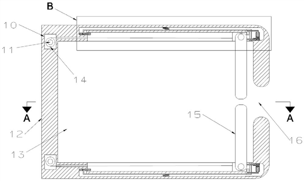
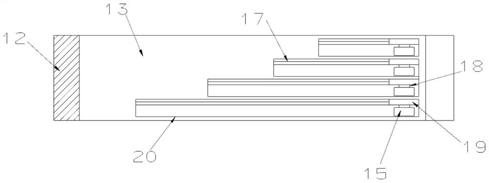
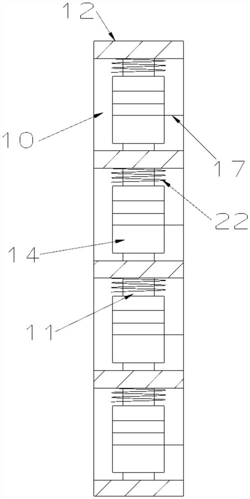
[0026] see Figure 1-Figure 9 , a network optical fiber cable management frame capable of automatic quantitative partitioning, including a cable management frame 60 and a cable management ring 12 installed on one side of the cable management frame 60, and the cable management ring 12 is arranged along the cable management frame 60 The extended direction of the cable is evenly installed, and the cable management ring 12 can be fixedly installed on the cable man...


PUM


Abstract

The invention relates to the technical field of communication network equipment. The invention discloses a network optical fiber arranging frame capable of realizing automatic quantitative partitioning. The arranging frame comprises a wire arranging frame and a wire arranging ring installed on one side of the wire arranging frame; one side of the wire arranging ring is provided with a gap; limiting sliding grooves arranged in the front-back direction are symmetrically formed in the upper inner wall and the lower inner wall of the wire arranging hole; the length difference value of the adjacentlimiting sliding grooves is fixed; a sliding block capable of sliding left and right is arranged in each limiting sliding groove; a hinge shaft is installed on the end face of one side of each sliding block, and a partition plate is installed on each hinge shaft in a hinged mode. The situation that optical fibers are all gathered at the gap of the wire arranging ring, and consequently the opticalfibers in the wire arranging ring need to be shifted inwards when the subsequent optical fibers are plugged into the wire arranging ring is avoided; the efficiency of the optical fibers entering thewire arranging ring is improved, and then the wire arranging efficiency is improved; and the width of each region for placing the optical fiber can accommodate the access of an optical fiber connector, so that the later maintenance, repair and replacement of the optical fibers are more convenient.

Description

technical field [0001] The invention relates to the technical field of communication network equipment, in particular to a network optical fiber cable management rack capable of automatic quantitative partitioning. Background technique [0002] The optical fiber cable management frame is an accessory device installed in the cabinet and used in conjunction with the distribution frame, which can make the optical fiber enter the cabinet distribution frame more smoothly and in parallel. Usually installed in the cabinet, the optical fiber cable management frame simplifies the planning and installation of the cross-connect system, makes the wiring line clearer and more beautiful, and is more convenient in future line expansion and management, improving the scalability of the system. At the same time, the bending radius of the optical fiber is increased during wiring to protect it from damage; [0003] At this stage, cable management racks with rings on one side are more commonly ...

Claims


Application Information

Patent Timeline
Patent Type & Authority Applications(China)
IPC IPC(8): G02B6/44
CPCG02B6/4452
Inventor 李珊珊
Owner 杭州三泽科技有限公司
Why Eureka
Try Eureka