Implantable Detectors for Medical Use

An implantable detector technology, applied in applications, sensors, medical science, etc., can solve the problems of narrow antenna frequency range, limited space size, affecting the quality of diagnosis, etc., and achieve wide antenna frequency range, reasonable structure, and good communication quality. Effect

Inactive Publication Date: 2016-06-08
吴端贝
View PDF7 Cites 0 Cited by
  • Summary
  • Abstract
  • Description
  • Claims
  • Application Information

AI Technical Summary

Problems solved by technology

However, implantable medical diagnostic devices have certain problems, including battery life, materials, etc., but one of the biggest problems is the quality of communication. Due to the limited space of implantable medical diagnostic devices, they are often placed in The antennas in it all have shortcomings such as narrow frequency range, poor isolation, and low gain, which seriously affect the quality of communication and thus the quality of diagnosis.

Method used


Image

  • Implantable Detectors for Medical Use
  • Implantable Detectors for Medical Use
  • Implantable Detectors for Medical Use

Examples


Embodiment 1

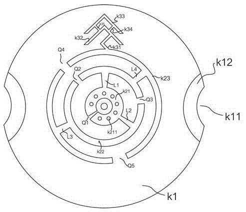
[0044] like Figure 1 to Figure 8As shown, a medical implantable detector described in this embodiment, a medical implantable detector, includes an electronic medical detection module, and also includes a communication device for making the electronic medical detection module communicate with the outside The antenna and the middle case 1 with an H-shaped cross-section, the top of the middle case 1 is provided with a first accommodating chamber for accommodating the electronic medical detection module; the bottom of the middle case 1 is provided with a second accommodating chamber; the second accommodating chamber An isolation plate 10 is arranged inside and above the middle shell 1; the communication antenna includes an upper antenna and a lower antenna; the lower antenna is arranged below the isolation plate 10 in the second accommodation cavity; The disc-shaped upper shell 3 above the isolation plate; the upper antenna is arranged in the disc-shaped upper shell 3; it also in...

Embodiment 2

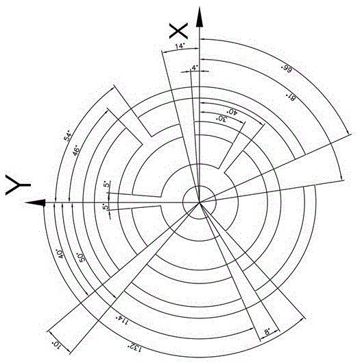
[0056] A medical implantable detector described in this embodiment, the radial width of the outer ring and the inner ring of the first circular ring arm K21 is 0.8cm-1.2cm; the radial width of the second circular ring arm K22 The radial width of the outer ring and the inner ring is 0.4cm-6cm; the radial width of the outer ring and the inner ring of the third ring arm K23 is 0.4cm-0.6cm. A medical implantable detector described in this embodiment, the radial width of the outer ring and the inner ring of the second ring arm K22 is the same as the radial width of the outer ring and the inner ring of the third ring arm K23 The radial width is the same. In the medical implantable detector described in this embodiment, the radial width of the outer ring and the inner ring of the first ring arm K21 is 1 cm. In the medical implantable detector described in this embodiment, the radial width of the outer ring and the inner ring of the third ring arm K23 is 0.5 cm. In the medical impla...


PUM


Abstract

The invention discloses a medical implantable detector, which includes an electronic medical detection module, a communication antenna for communicating the electronic medical detection module with the outside, and a middle shell with an H-shaped cross section. The first accommodation chamber for housing the electronic medical detection module; the second accommodation chamber is provided under the middle housing; the isolation plate is arranged in the second accommodation chamber and above the middle housing; the structure is reasonable, no tingling sensation to the human body, The internal structure is set reasonably, the frequency range of the antenna placed inside it is wide, the isolation is good, and the gain is high; it provides a good installation module for the research and development of implantable medical diagnostic devices, and each company only needs to implant its own The type electronic medical unit is designed to be able to be placed in the shape and thickness or size of the bottom shell, so as to achieve better communication quality.

Description

technical field [0001] The invention relates to an implanted detector for medical use. Background technique [0002] At present, there are many types of implanted medical devices, such as implanted cardiac pacemakers, brain pacemakers, nerve stimulators, muscle stimulators, ECG recorders, etc., and now there are diagnostic devices implanted in the human body. For real-time diagnosis of patient's heartbeat, pulsation, blood pressure or other information, such as the implantable instrument disclosed in 201410134849.8, it still needs to communicate with the outside world in order to transmit the information in real time. At present, the diagnostic device generally consists of a uniquely designed small device box and an implanted electronic medical unit in the device box; plus an antenna for connecting the implanted electronic medical unit to the outside world, the implanted electronic medical unit generally Contains detection circuit, detector, battery, etc. However, implanta...

Claims


Application Information

Patent Timeline
Patent Type & Authority Patents(China)
IPC IPC(8): A61B5/00A61B5/02H01Q1/22H01Q1/36H01Q1/38H01Q13/08
Inventor 吴端贝
Owner 吴端贝
Why Eureka
Try Eureka