Multistep pressure coding detonating method and device for well perforation

A detonation method and pressure technology, which are used in earth-moving drilling, wellbore/well components, and production fluids, etc., can solve the problem that the delay time of detonation cannot be changed, the monitoring of the underground working environment cannot be realized, the test joint cannot be performed, and the pump cannot be used. Perforating and perforating technology and other issues

Active Publication Date: 2016-01-13
WUHUA ENERGY TECH CO LTD
View PDF7 Cites 8 Cited by
  • Summary
  • Abstract
  • Description
  • Claims
  • Application Information

AI Technical Summary

Problems solved by technology

This method also cannot be used in the construction of highly deviated wells and horizontal wells, nor can it be used in perforation processes such as test joints and perforation with pumps.
[0013] The detonation method of mode 3 is applicable to almost all well conditions, so it is the most widely used method. However, after the delay initiator is lowered into the well, the delay time of detonation cannot be changed due to the fixed delay time; When there is a delay condition, it is necessary to increase the number of delay detonators, which increases the equipment volume, complexity and cost; it is impossible to realize the monitoring of the downhole working environment (parameters such as working pressure and ambient temperature)
[0014] In addition, in the ignition process of the above methods, a single pressure value is used to stimulate the detonation. Due to the variability of the downhole environment and the pressure detection method is too simple, the pressure detection is inaccurate, prone to false detonation, resulting in engineering accidents, construction delays and property damage. loss

Method used


Image

  • Multistep pressure coding detonating method and device for well perforation
  • Multistep pressure coding detonating method and device for well perforation

Examples


Embodiment Construction

[0043] Now in conjunction with embodiment, accompanying drawing, the present invention will be further described:

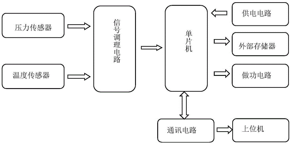
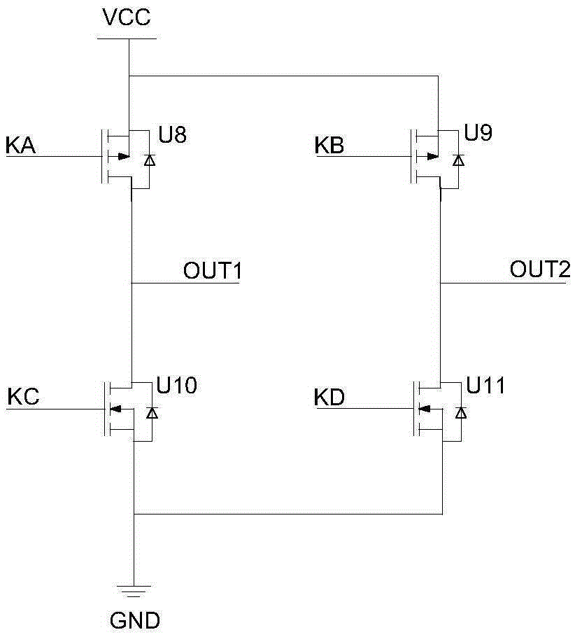
[0044] attached figure 1 It is a functional block diagram of the device for the multi-stage pressure coding detonation method of oil well perforation according to the present invention, including pressure sensor, temperature sensor, signal conditioning circuit, single-chip microcomputer, power supply circuit, external storage, working circuit and communication circuit. The working circuit includes four field effect transistors U8, U9, U10 and U11, the four field effect transistors are connected with the source and drain to form a bridge connection, and the connection between the source of U8 and the drain of U10 is the output terminal OUT1. The connection end of the source of U9 and the drain of U11 is the output terminal OUT2, and the grids KA, KB, KC, and KD of the four field effect transistors are respectively connected with the I / O ports of the single-chip mi...


PUM


Abstract

The invention relates to a multistep pressure coding detonating method and device for well perforation. The method comprises the following steps: detecting pressure and temperature signals of a position of well perforation through a pressure sensor and a temperature sensor in real time, comparing the temperature signal with a temperature set by a temperature switch, and starting detonating signal identification after the temperature signal reaches or exceeds the temperature set by the temperature switch; comparing the received pressure signal with a pre-stored and set starting pressure command and completing starting pressure command identification; comparing a subsequently received pressure signal with a pre-stored and set pressure coding command, comparing the received pressure signal with a preset positive coding command and a preset negative coding command, and when a pressure signal detected underground conforms to the set positive coding command, sending a positive acting command to an acting circuit and controlling the acting circuit to output a positive-polarity voltage to detonate a perforating bullet, thereby realizing primary perforating gun detonation; by means of the same principle, negative detonating perforation can be realized.

Description

technical field [0001] The invention belongs to the automatic control technology in the field of petroleum, and relates to a multi-stage pressure coding detonation method and device for oil well perforation. Background technique [0002] In the field of petroleum, as an important natural resource, petroleum occupies a pivotal position in the process of my country's economic and social development. Since the reform and opening up, with the rapid development of my country's economic construction, the dependence on natural resources, especially oil, has become increasingly apparent. my country is a country that lacks oil, and more than half of its demand needs to be imported every year. Correspondingly, the development of petroleum instruments in our country is also at a relatively backward level in the world. Increase the development of advanced petroleum instruments and improve To improve oil production efficiency and obtain higher output is a very urgent problem facing our c...

Claims


Application Information

Patent Timeline
Patent Type & Authority Applications(China)
IPC IPC(8): E21B43/1185
Inventor 罗兴平杨伟俞海刘正彦闵杰王雪艳同剑赵云涛王峰刘西京
Owner WUHUA ENERGY TECH CO LTD
Why Eureka
Try Eureka