
Steam turbine flow curve identifying and optimizing method based on spray nozzle flow calculation

A technology of flow calculation and optimization method, applied in mechanical equipment, engine components, machines/engines, etc., can solve problems such as affecting the safe and stable operation of the unit, valve switching load fluctuations, and inconsistency in the setting curve of the flow characteristics of the regulating valve group.

Active Publication Date: 2016-01-13
STATE GRID HENAN ELECTRIC POWER ELECTRIC POWER SCI RES INST +3
View PDF9 Cites 7 Cited by
  • Summary
  • Abstract
  • Description
  • Claims
  • Application Information

AI Technical Summary

Problems solved by technology

[0002] Steam turbine is the most widely used prime mover in modern thermal power plants, and the flow characteristic curve of its regulating valve group is determined according to the original design. In overhauled units, it often happens that the flow characteristic setting curve of the valve group is inconsistent with the actual curve
As the main actuator of the DEH system, the steam turbine valve group is the main actuator of the DEH system. If the deviation of its flow characteristics is too large, the throttling loss of the steam turbine will increase, the response load of primary frequency regulation will be insufficient or too large, the AGC response will be slow, and the valve switching load will fluctuate. Safe and stable operation of the unit

Method used


Image

  • Steam turbine flow curve identifying and optimizing method based on spray nozzle flow calculation
  • Steam turbine flow curve identifying and optimizing method based on spray nozzle flow calculation
  • Steam turbine flow curve identifying and optimizing method based on spray nozzle flow calculation

Examples


Embodiment Construction

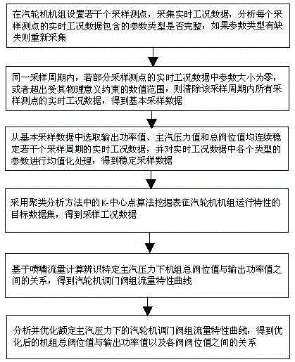
[0028] Such as figure 1 As shown, the steam turbine flow curve identification and optimization method based on nozzle flow calculation according to the present invention comprises the following steps:

[0029] A. Set several sampling measuring points in the steam turbine unit, and set the sampling cycle and sampling time, collect the real-time working condition data of the steam turbine unit, and analyze whether the parameter types contained in the real-time working condition data of each sampling measuring point are complete. If the parameters If the type is missing, it will be collected again. If the parameter type is not missing, go to step B.

[0030] B. For all sampling points, if within the same sampling period, the real-time working condition data of one or more sampling measuring points has a parameter size of zero, that is, there is a blank working condition data, or the parameter size exceeds the constraints of its physical meaning In other words, when there is abno...


PUM


Abstract

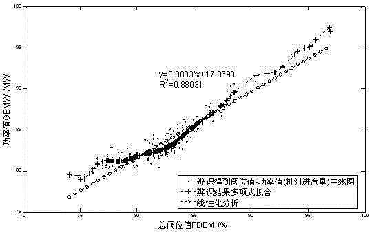
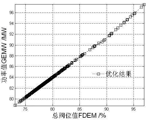
The invention discloses a steam turbine flow curve identifying and optimizing method based on spray nozzle flow calculation. The steam turbine flow curve identifying and optimizing method comprises the following steps: A, setting a plurality of sampling measure points, and acquiring real-time working condition data; B, clearing vacant working condition data and abnormal working condition data; C, selecting the real-time working data that an output power value, a primary steam pressure value and a total valve location value are continuously stabilized for a plurality of sampling periods, and carrying out equalization processing on various parameters; D, adopting a K-center clustering algorithm to excavate a target data set; E, based on spray nozzle flow calculation, identifying a steam turbine control valve set flow characteristic curve under special primary steam pressure; and F, extracting the steam turbine control valve set flow characteristic curve under rated primary steam pressure, and analyzing and optimizing a region with unreasonable degree of linearity. According to the steam turbine flow curve identifying and optimizing method, a practical flow characteristic curve, under special primary steam pressure, of the steam turbine control valve set can be identified and optimized, so that the control valve set flow characteristic setting curve is consistent with the practical curve, and therefore, safe and stable operation of a steam turbine unit is guaranteed.

Description

technical field [0001] The invention relates to the technical field of steam turbine power generation, in particular to a steam turbine flow curve identification and optimization method based on nozzle flow calculation. Background technique [0002] Steam turbine is the most widely used prime mover in modern thermal power plants, and the flow characteristic curve of its regulating valve group is determined according to the original design. In overhauled units, it often happens that the flow characteristic setting curve of the regulating valve group is inconsistent with the actual curve. As the main actuator of the DEH system, the steam turbine valve group is the main actuator of the DEH system. If the deviation of its flow characteristics is too large, the throttling loss of the steam turbine will increase, the response load of primary frequency regulation will be insufficient or too large, the AGC response will be slow, and the valve switching load will fluctuate. The safe...

Claims


Application Information

Patent Timeline
IPC IPC(8): F01D17/00
Inventor 粱正玉杨涛王刚郭为民韩威李存文王纪宏唐耀华郝涛
Owner STATE GRID HENAN ELECTRIC POWER ELECTRIC POWER SCI RES INST
Learn More