Method and device for fatigue testing of exhaust valve disc

A fatigue test and exhaust valve technology, applied in the direction of measuring device, mechanical component test, machine/structural component test, etc., can solve the problem of small impact speed of valve plate, insignificant test effect, and inability to obtain better test effect, etc. problem, to achieve the effect of accurate test results

Active Publication Date: 2018-06-01
GREE ELECTRIC APPLIANCES INC +1
View PDF6 Cites 0 Cited by
  • Summary
  • Abstract
  • Description
  • Claims
  • Application Information

AI Technical Summary

Problems solved by technology

[0006] For example, a fatigue testing machine is provided in a patent, the valve plate is opened and closed by driving the punch through the slider, the valve plate and the punch are always in contact, the number of punches is the same as the number of the valve plate, once The life test of multiple valve plates can be carried out, but this method is mainly to simulate the contact bending fatigue performance of the valve plate, the impact velocity of the valve plate is small, and it is accompanied by the surface wear of the valve plate material, which is inconsistent with the actual situation
[0007] Another patent provides a life test device for compressor valve slices. By setting the electromagnet, and according to the design requirements, the electromagnet will be turned on and off at a set frequency, and the electromagnet will intermittently turn on and off according to the set frequency. Adsorb the valve plate, so that the valve plate impacts the electromagnet and taps the exhaust port intermittently according to the set frequency. The main problem is that the existing valve plate material has poor magnetic conductivity, and the test effect is not obvious.
[0008] None of the existing fatigue test methods can accurately simulate the force of the valve plate, so none of them can obtain good test results

Method used


Image

  • Method and device for fatigue testing of exhaust valve disc
  • Method and device for fatigue testing of exhaust valve disc
  • Method and device for fatigue testing of exhaust valve disc

Examples


Embodiment Construction

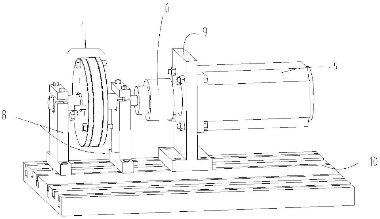
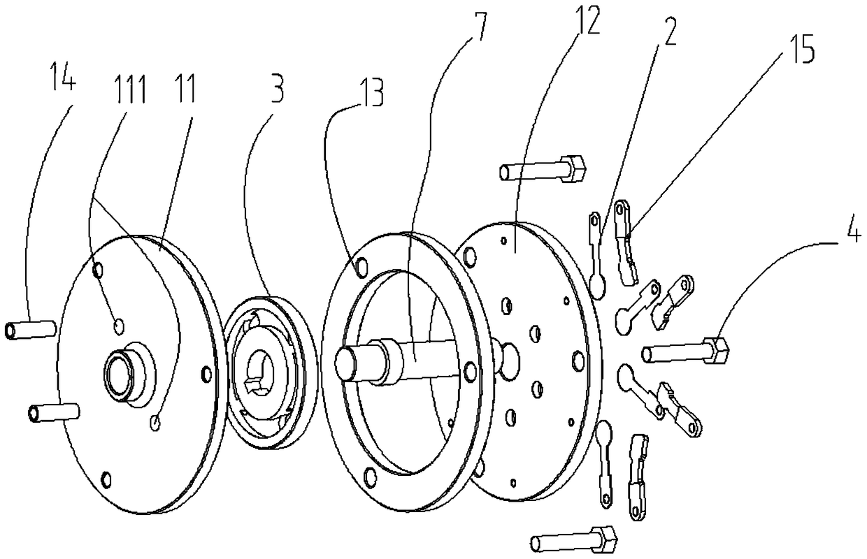
[0040] The technical solutions of the present invention will be further described below in conjunction with the accompanying drawings and through specific implementation methods.

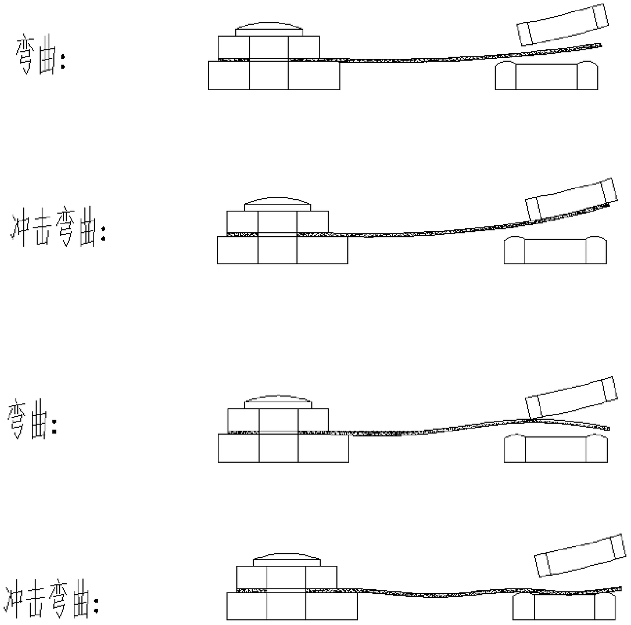
[0041] The present invention provides a fatigue test method for the valve plate of the exhaust valve, which fixes one end of the valve plate and performs the following actions in a cycle:

[0042] Exhaust action, using compressed air to impact the free end of the valve plate, causing the valve plate to bend, simulating the shape of the valve plate when it is exhausted;

[0043] The reset action stops the impact of compressed air on the free end of the valve plate, and the free end of the valve plate resets, simulating the reset state of the valve plate stopping exhaust.

[0044] The above-mentioned exhaust and reset actions are carried out cyclically by the valve plate to accurately simulate the force of the valve plate, so as to truly evaluate the reliability of the exhaust structure and materials,...


PUM


Abstract

The invention discloses a method and a device for fatigue testing of an exhaust valve disc, and relates to the technical field of fatigue testing. The fatigue test method of the valve plate of the exhaust valve is as follows: one end of the valve plate is fixed, and the following actions are performed in a cycle: exhaust action, use compressed air to impact the free end of the valve plate, and the valve plate is bent; reset action, The impact of the compressed air on the free end of the valve plate is stopped, and the free end of the valve plate is reset. At the same time, a device for fatigue testing of exhaust valve discs using the above method is proposed. The exhaust valve disc fatigue test method provided by the present invention uses compressed air to impact the valve disc to make the valve disc bend, which can accurately simulate the stress of the valve disc, truly evaluate the reliability of the exhaust structure and materials, and obtain accurate results. Test Results.

Description

technical field [0001] The invention relates to the technical field of valve plate fatigue testing, in particular to a fatigue testing method for a valve plate of an exhaust valve and a device using the method. Background technique [0002] The combination of the exhaust valve plate and the pump body parts can establish the suction and discharge pressure, which is one of the key parts in the refrigeration compressor. With the popularization of compressor frequency conversion technology, the number of openings of the exhaust valve per unit time has increased significantly, and the requirements for the fatigue performance of the valve are getting higher and higher. Since the service life of the refrigeration compressor is required to be more than 10 years, for this requirement, the fatigue of the valve plate is a key component of the pump body, and it is even more necessary to add specific tests to verify the reliability of the material of the valve plate. [0003] It can be ...

Claims


Application Information

Patent Timeline
Patent Type & Authority Patents(China)
IPC IPC(8): G01M13/00
Inventor 史正良李佑褔任洋单彩侠
Owner GREE ELECTRIC APPLIANCES INC
Why Eureka
Try Eureka