Horizontal drop fuse

A drop-out fuse, horizontal technology, applied in the direction of electrical components, circuits, emergency protection devices, etc., can solve the problems of visual blind spots and inconvenient operation

Active Publication Date: 2016-01-13
TIELING POWER SUPPLY COMPANY OF STATE GRID LIAONING ELECTRIC POWER COMPANY +1
View PDF6 Cites 2 Cited by
  • Summary
  • Abstract
  • Description
  • Claims
  • Application Information

AI Technical Summary

Problems solved by technology

[0003] The present invention aims at the problems existing in the above-mentioned prior art, and provides a h...

Method used


Image

  • Horizontal drop fuse
  • Horizontal drop fuse

Examples


Embodiment

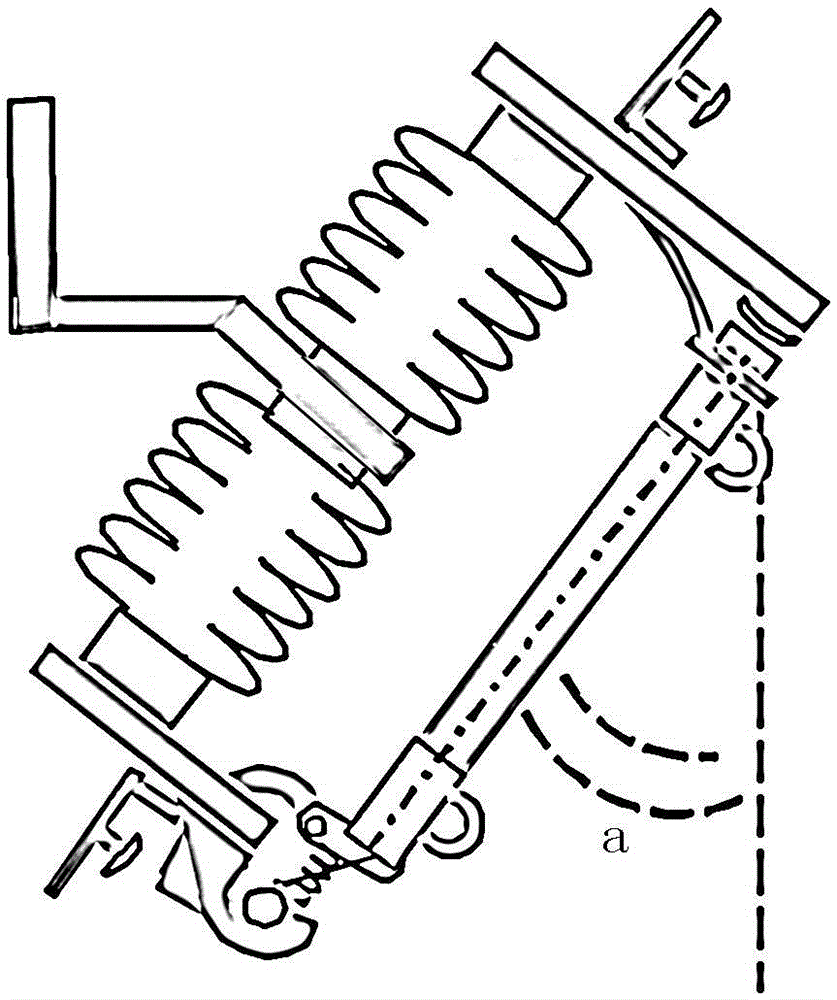
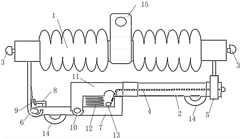
[0017] Such as figure 2 As shown, the fuse includes an insulating ceramic column 1, a fuse tube 2 and terminals 3 at both ends, and the fuse 4 is arranged in the fuse tube 2; a connecting plate 15 for connecting the equipment frame is arranged on the insulating ceramic column, and the insulating ceramic column 1 and the fuse tube 2 are placed horizontally, one end of the fuse tube 2 is connected to the head chuck 5, the other end of the fuse tube 2 is connected to one end of the conductive arm 7, and the other end of the conductive arm 7 is connected to the tail hanging hook 6; An L-shaped contact 8 and a reed 9 are arranged between the conductive arm 7 and the tail hanging hook 6 .

[0018] The conductive arm is L-shaped, and the L-shaped conductive arm is connected with a fixed plate 11 through a movable shaft 10, and a spring 12 is arranged between the fixed plate 11 and the L-shaped conductive arm; The L-shaped conductive arms 7 are connected; a semicircular operating ri...


PUM


Abstract

The invention relates to a horizontal drop fuse, comprising an insulated porcelain column, a fuse tube and two end connection terminals, wherein a fuse is arranged in the fuse tube; the insulated porcelain column and the fuse tube are placed horizontally, one end of the fuse tube is connected with a head chuck, the other end of the fuse tube is connected with one end of a conductive arm, and the other end of the conductive arm is connected with a tail suspender; and a contact and a reed are arranged between the conductive arm and the tail suspender. Because the fuse tube is placed horizontally, the operation angle of a pull rod is very good, and the fuse can be conveniently opened or closed. The horizontal drop fuse also facilitates visual check of equipment due to good observation angle.

Description

technical field [0001] The invention relates to a fuse, in particular to a horizontal drop-out fuse. Background technique [0002] Such as figure 1 As shown, the drop-out fuse in the prior art generally installs the support iron of the fuse at the upper and lower ends of the insulating ceramic column, and the fuse tube is fixed on the fuse through the contact spring at the upper end, the hanging hook, the pressure plate and the shackle at the lower end. On the device, when the fuse is blown, the lower locking mechanism will loosen, and under the influence of gravity, the upper end of the fuse tube will be separated from the upper hanging hook, and the entire fuse tube will swing in a circular arc around the lower hook ring as the center. hanging on the fuse. Since the inclination angle a is 20-30 degrees during design and installation, and the installation position of the fuse is very high, when the personnel use the operating lever for power transmission operation, the op...

Claims


Application Information

Patent Timeline
IPC IPC(8): H01H85/54
CPCH01H85/54
Inventor 钱勇曹红梅周雁叶柳姜丽艳惠晶晶高左军葛新王笑冰
Owner TIELING POWER SUPPLY COMPANY OF STATE GRID LIAONING ELECTRIC POWER COMPANY
Why Eureka
Try Eureka