
A digital delay implementation method and circuit for integrated circuits

A digital delay, integrated circuit technology, applied in the field of digital delay implementation methods and circuits, can solve problems such as delay time limitation, and achieve the effects of reducing the number of bits of adders, shortening logic delay, and reducing logic area

Active Publication Date: 2018-03-20
SG MICRO
View PDF5 Cites 0 Cited by
  • Summary
  • Abstract
  • Description
  • Claims
  • Application Information

AI Technical Summary

Problems solved by technology

This method is a compromise between the above two methods. Although the area of ​​the adder and related combinational logic circuits is reduced, the delay time also has a certain limit, which is n×T period ×2 N , where T period is the input clock period, n is any natural number, N is the number of cascaded D flip-flops, and the counting target is n×2 N , must be even
This method no longer works when the count target is odd

Method used


Image

  • A digital delay implementation method and circuit for integrated circuits
  • A digital delay implementation method and circuit for integrated circuits
  • A digital delay implementation method and circuit for integrated circuits

Examples


Embodiment Construction

[0030] Embodiments of the present invention will be described in further detail below in conjunction with the accompanying drawings.

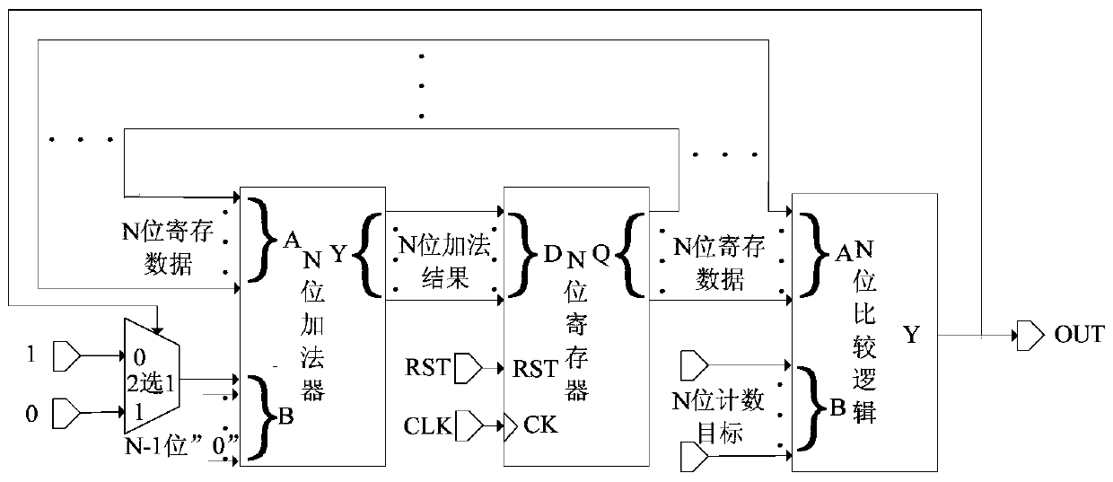
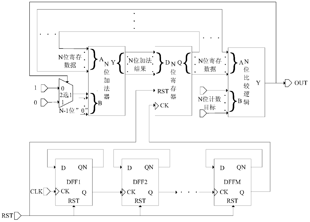
[0031] In order to complete the delay function, the digital circuit must be based on the clock. Under the fast clock, simply using the counting method to complete a long time delay will produce a large counting target, which requires combinational logic such as a multi-bit adder. Using frequency division to increase the clock period is an effective way to reduce the number of combinational logic bits such as adders. In order to ensure that the delay time is not limited by the frequency division of the clock, the design idea of ​​the present invention is to use clocks with different frequency division numbers instead of a frequency division clock with a single frequency as required.

[0032] A digital delay implementation method for integrated circuits, comprising the following steps:

[0033] Step 1) According to the delay time T delay with ...


PUM


Abstract

The invention provides a digital delay implementation method and circuit for integrated circuits, which can not only realize the delay of n×Tperiod duration, where Tperiod is the input clock period, n is any natural number, and at the same time greatly reduces the number of adders , reducing the combinatorial logic area and shortening the logic delay. The method of the present invention comprises: 1) determine delay total number M according to delay time Tdelay and clock cycle Tperiod, and M is converted into binary code bN-1...bj...b1b0 by decimal system; 2) determine count target U: convert M The resulting binary code bN-1...bj...b1b0 is added to the coefficients before bj=1 to obtain the counting target U, and U is converted from decimal to binary code bP-1...bi...b1b0; 3) According to the counting target U obtained, The method of direct counting is adopted after frequency division by the frequency division method of changing the counting step size, so as to realize the delay of n×Tperiod duration, where Tperiod is the input clock period, and n is any natural number.

Description

technical field [0001] The invention relates to the technical field of integrated circuits, in particular to a digital delay realization method and circuit for integrated circuits. Background technique [0002] At present, the implementation of digital delay circuits is generally based on the number of input clocks to complete the delay function, without the need for resistors and capacitors, and can be realized through a digital design top-down process. It can be mainly divided into the following three implementation methods: [0003] 1.D flip-flop cascade method, such as figure 1 shown. In this method, N cascaded D flip-flops are included, and the reverse output terminal QN of each stage of D flip-flop is connected to the input terminal D of this stage, and the clock output QN of the D flip-flop is connected to the clock of the next-stage D flip-flop The input terminal CK is connected, and the clock input terminal CK of the first-level D flip-flop is connected to the cl...

Claims


Application Information

Patent Timeline
Patent Type & Authority Patents(China)
IPC IPC(8): H03K5/133
Inventor 张波张利地张海冰
Owner SG MICRO
Learn More