Vacuum wall crawler

A crawler and vacuum technology, applied in the field of toothed belts, can solve problems such as expensive and complex manufacturing, and achieve the effect of a simple solution

Active Publication Date: 2016-01-20
FORCE TECH
View PDF7 Cites 15 Cited by
  • Summary
  • Abstract
  • Description
  • Claims
  • Application Information

AI Technical Summary

Problems solved by technology

Consequently, the internals in both devices for distributing the vacuum are heavier, more complex and expensive complex mechanisms to manufacture

Method used


Image

  • Vacuum wall crawler
  • Vacuum wall crawler
  • Vacuum wall crawler

Examples


Embodiment Construction

[0061] In the following detailed description, the vacuum wall crawler 1 and the adsorption crawler unit 100 according to the present invention will be described through preferred embodiments.

[0062] The construction and operation of the vacuum wall crawler 1 is well known and therefore requires no further explanation in context. However, further details regarding the operation of the vacuum wall crawler 1 are provided below.

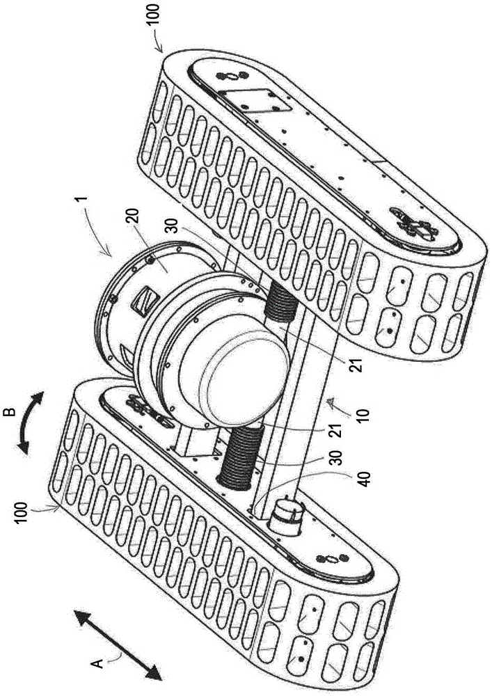
[0063] figure 1 A first exemplary embodiment of a vacuum wall crawler 1 is shown.

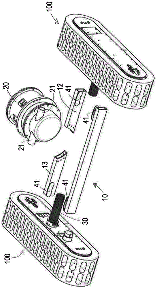
[0064] The vacuum wall crawler 1 is a mobile device that can be attached to a surface (eg a wall or ceiling etc.) by using one or more suction crawler units 100 . figure 1 The vacuum wall crawler 1 shown in has two suction crawler units 100 . The suction track unit 100 is connected to the main frame 10 by a joint 40 which allows the vacuum wall crawler 1 to adapt to the curved surface on which it travels, see below.

[0065] In other embodiments (not shown), the vac...


PUM


Abstract

The present invention relates to a vacuum wall crawler (1) having at least one vacuum track unit (100) comprising: a track frame (150); two pulleys (140, 141) provided in opposite ends of the track frame (150), and defining a wheelbase (W); an endless track (110) arranged to circulate on the two pulleys (140, 141), and comprising a flexible band (120), said flexible band (120) comprising a plurality of apertures (123), and having a thickness (T); a vacuum distribution box (200) provided in said track frame (150) wherein the vacuum distribution box (200) is in communication with a portion of the apertures (123) to distribute a vacuum to the portion of apertures (123) as the endless track (110) circulates, where the thickness (T) of the flexible band (120) is 5-20% of the wheel base, W.

Description

[0001] The invention relates to a vacuum wall crawler (crawler, crawler traction device) comprising at least one suction crawler unit of the type having an endless crawler comprising a continuous belt formed of a flexible material having multiple An orifice for providing a vacuum between a portion of the orifice and the surface on which the vacuum wall crawler rests or moves. Background technique [0002] For performing a variety of tasks such as inspection, cleaning and rust removal, removal of radioactive contamination and For repairs, the use of automatic working devices operable by remote control to avoid the presence of humans in often dangerous places is known in the art. An example of such a robotic working device is a vacuum wall crawler that can carry a tool or camera etc. close to a vertical, inverted, sloped, curved, composite or tapered surface and move the tool to multiple points on the surface. locations. Some common scenarios include inspecting, cleaning, remo...

Claims


Application Information

Patent Timeline
Patent Type & Authority Applications(China)
IPC IPC(8): B62D55/265
CPCB62D55/265B62D55/075
Inventor 斯滕·阿恩弗雷兹·尼尔森佩德·本特·汉森
Owner FORCE TECH
Why Eureka
Try Eureka