
Connection ring and automatic x-ray controller

An X-ray and connecting ring technology, applied in the field of medical equipment, can solve problems such as X-ray exposure of patients and achieve the effect of protecting patients

Active Publication Date: 2018-03-27
上海汉缔医疗设备有限公司
View PDF6 Cites 0 Cited by
  • Summary
  • Abstract
  • Description
  • Claims
  • Application Information

AI Technical Summary

Problems solved by technology

Therefore, the conventional dental X-ray apparatus has the problem of exposing patients to unnecessary X-rays

Method used


Image

  • Connection ring and automatic x-ray controller
  • Connection ring and automatic x-ray controller
  • Connection ring and automatic x-ray controller

Examples


specific Embodiment approach

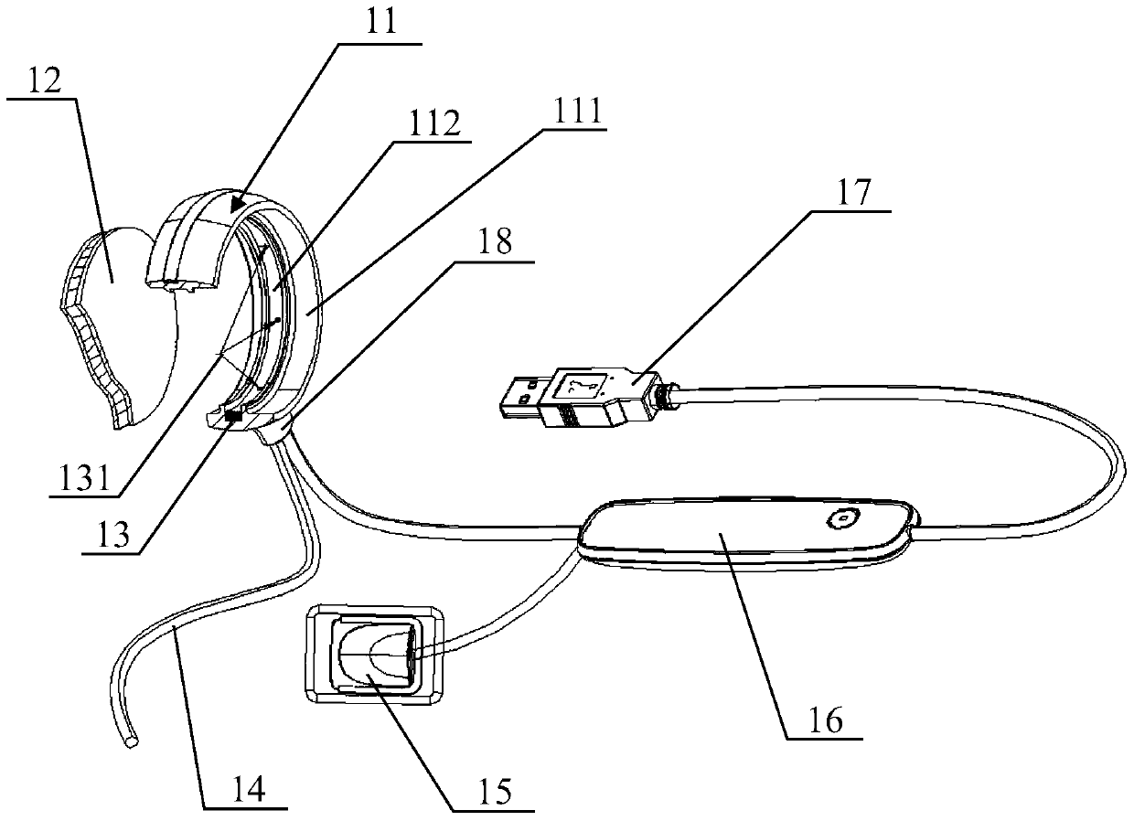
[0022] figure 1 is a schematic diagram of the overall structure of the X-ray automatic controller of the present invention, figure 1 A partial cross-sectional structure is shown in the connecting ring and the X-ray blocking plate. Such as figure 1 As shown, the X-ray automatic controller has a connection ring 11 , an X-ray blocking plate 12 , a blocking liquid chamber 13 , a power cord 14 , a sensor 15 , a controller 16 and a USB data interface 17 .

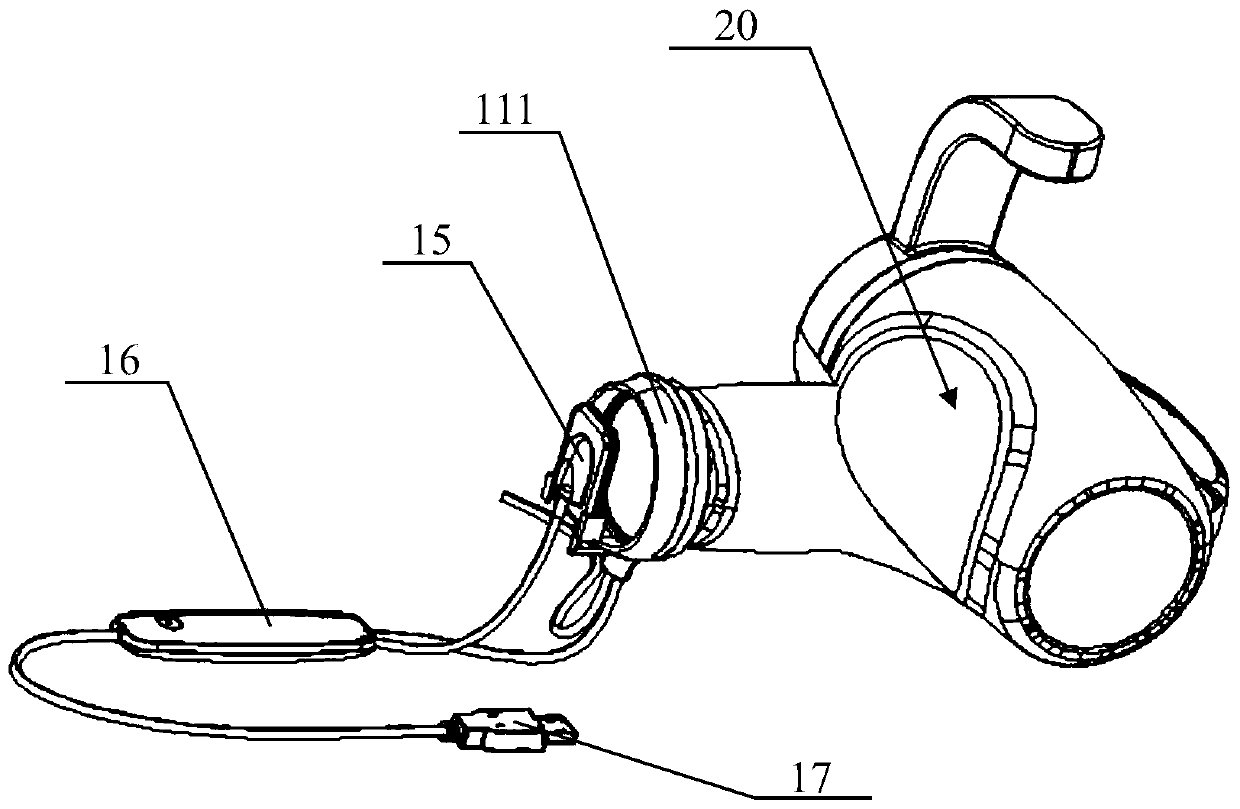
[0023] An annular connecting sleeve 111 , an annular fitting groove 112 , and an X-ray blocking plate 12 are provided in the ring of the connecting ring 11 . The X-ray blocking plate 12 is circular and embedded in the fitting groove 112 . Such as figure 2 As shown, the connecting sleeve 111 is sleeved at the X-ray outlet of the X-ray emitter 20 .

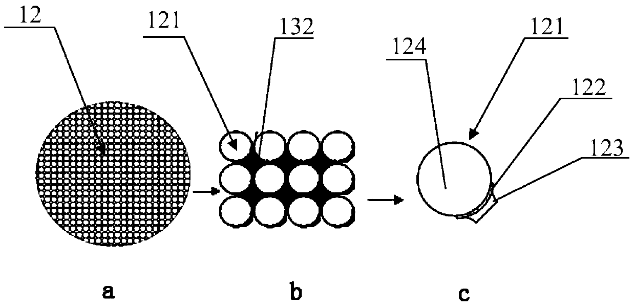
[0024] The structure of the X-ray blocking plate 12 is as follows: image 3 As shown, among them, image 3 a is the overall structure of the X-ray blocking plate 12. The X-ray ...


PUM


Abstract

The invention provides a connecting ring, which is set on the X-ray generator of the dental X-ray apparatus to control the radiation dose of X-rays. It is characterized in that it comprises: a connecting sleeve connected with the X-ray outlet of the X-ray generator; And the X-ray blocking plate is embedded in the middle of the connecting sleeve. There are multiple particle cavities inside the X-ray blocking plate. The gaps between the particle cavities are filled with X-ray blocking liquid. The upper and lower sides of the particle cavity are magnetic films. , There is a valve between the films. In the initial state, the valve is closed, and the upper and lower films are attracted to each other; in the use state, the lower valve is opened, and the upper and lower films are separated from each other, and the X-ray blocking liquid enters the interior of the particle chamber. The connection ring of the present invention can block redundant X-rays penetrating around the teeth and protect tissues from X-rays, thereby achieving the purpose of protecting patients.

Description

technical field [0001] The invention relates to a connecting ring, and also relates to an X-ray automatic controller, which belongs to the field of medical equipment. Background technique [0002] In the process of dental diagnosis, it is often necessary to use a dental X-ray machine to take X-ray pictures of teeth to help diagnosis. The X-rays emitted by the traditional dental X-ray apparatus are directly irradiated on the detected tissue in the oral cavity, but because the X-ray irradiation range is larger than the actual range required for diagnosis, the patient will be exposed to a large dose of X-rays, Exposure to unnecessary X-rays. In addition, the angle and position of the X-ray irradiation need to be adjusted before taking pictures to obtain the best viewing angle. During the adjustment process, the X-ray is always on, and the patient will also be exposed to the X-ray during the process. Therefore, the conventional dental X-ray apparatus has a problem of exposing ...

Claims


Application Information

Patent Timeline
Patent Type & Authority Patents(China)
IPC IPC(8): A61B6/14A61B6/10
Inventor 韩愚陈强江
Owner 上海汉缔医疗设备有限公司
Learn More