
Connecting ring and X-ray automatic controller

An X-ray and connecting ring technology, applied in the field of medical equipment, can solve problems such as X-ray exposure of patients and achieve the effect of protecting patients

Active Publication Date: 2016-01-27
上海汉缔医疗设备有限公司
View PDF6 Cites 0 Cited by
  • Summary
  • Abstract
  • Description
  • Claims
  • Application Information

AI Technical Summary

Problems solved by technology

Therefore, the conventional dental X-ray apparatus has the problem of exposing patients to unnecessary X-rays

Method used


Image

  • Connecting ring and X-ray automatic controller
  • Connecting ring and X-ray automatic controller
  • Connecting ring and X-ray automatic controller

Examples


specific Embodiment approach

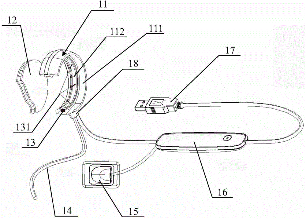
[0022] figure 1 is a schematic diagram of the overall structure of the X-ray automatic controller of the present invention, figure 1 A partial cross-sectional structure is shown in the connecting ring and the X-ray blocking plate. Such as figure 1 As shown, the X-ray automatic controller has a connection ring 11 , an X-ray blocking plate 12 , a blocking liquid chamber 13 , a power cord 14 , a sensor 15 , a controller 16 and a USB data interface 17 .

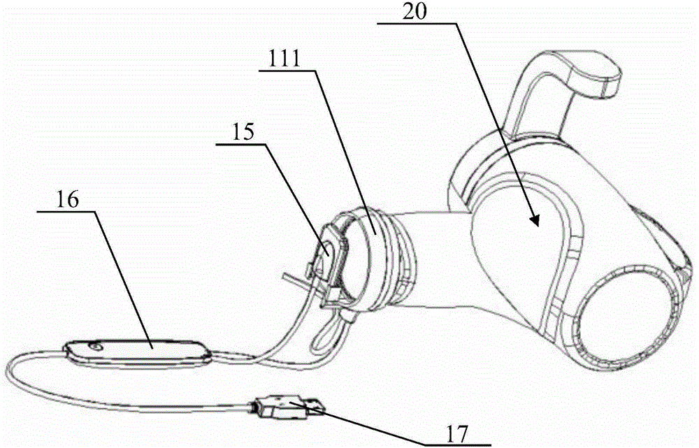
[0023] An annular connecting sleeve 111 , an annular fitting groove 112 , and an X-ray blocking plate 12 are provided in the ring of the connecting ring 11 . The X-ray blocking plate 12 is circular and embedded in the fitting groove 112 . Such as figure 2 As shown, the connecting sleeve 111 is sleeved at the X-ray outlet of the X-ray emitter 20 .

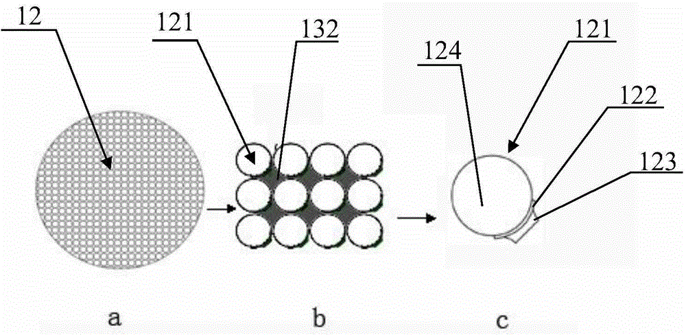
[0024] The structure of the X-ray blocking plate 12 is as follows: image 3 As shown, among them, image 3 a is the overall structure of the X-ray blocking plate 12. The X-ray ...


PUM


Abstract

The invention provides a connecting ring which sleeves on an X-ray generator of a dentistry X-ray machine and used for controlling the exposure of X-ray. The connecting ring is characterized by comprising a connecting sleeve and an X-ray barrier plate. The connecting sleeve is connected to an X-ray exit of the X-ray generator. The X-ray barrier plate is embedded in the middle portion of the connecting sleeve, the X-ray barrier plate has a plurality of particle chambers in the interior, a X-ray barrier liquid is filled in gaps among the particle chambers, magnetic films are arranged on and under the particle chambers, a valve is arranged between the films. In the initial state, the valve is closed, the upper and lower films mutually attract. When the connecting ring is used, the valve is opened, the upper and lower films separate from each other, and the X-ray barrier liquid enters into the particle chambers. The connecting ring can block superfluous X-ray penetrating the periphery of teeth, and protect tissue from being irradiated by the X-ray, so as to protect patients.

Description

technical field [0001] The invention relates to a connecting ring, and also relates to an X-ray automatic controller, which belongs to the field of medical equipment. Background technique [0002] In the process of dental diagnosis, it is often necessary to use a dental X-ray machine to take X-ray pictures of teeth to help diagnosis. The X-rays emitted by the traditional dental X-ray apparatus are directly irradiated on the detected tissue in the oral cavity, but because the X-ray irradiation range is larger than the actual range required for diagnosis, the patient will be exposed to a large dose of X-rays, Exposure to unnecessary X-rays. In addition, the angle and position of the X-ray irradiation need to be adjusted before taking pictures to obtain the best viewing angle. During the adjustment process, the X-ray is always on, and the patient will also be exposed to the X-ray during the process. Therefore, the conventional dental X-ray apparatus has a problem of exposing ...

Claims


Application Information

Patent Timeline
Patent Type & Authority Applications(China)
IPC IPC(8): A61B6/14A61B6/10A61B6/51
Inventor 韩愚陈强江
Owner 上海汉缔医疗设备有限公司
Learn More