Eureka AIR delivers breakthrough ideas for toughest innovation challenges, trusted by R&D personnel around the world.

Lifting appliance for cylinder

A spreader and cylinder technology, applied in the spreader field, can solve the problems of easy falling, safety accident, wear and so on, and achieve the effect of easy clamping

Active Publication Date: 2016-01-27
ANHUI QUANCHAI ENGINE
View PDF6 Cites 4 Cited by
  • Summary
  • Abstract
  • Description
  • Claims
  • Application Information

AI Technical Summary

Problems solved by technology

The traditional cylinder hoist is generally a simple hook, which needs to be manually righted to ensure the stability of the cylinder during hoisting. The hoisting process has the disadvantages of being unstable and easy to fall, which is likely to cause safety accidents, and the joint surface between the hook and the main shaft cover during the hoisting process Contact causes early wear of the lower main shaft cover, which affects the performance of the diesel engine

Method used


Image

  • Lifting appliance for cylinder
  • Lifting appliance for cylinder

Examples


Embodiment Construction

[0024] The present invention will be described in detail below in conjunction with the accompanying drawings.

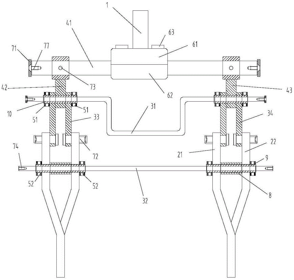
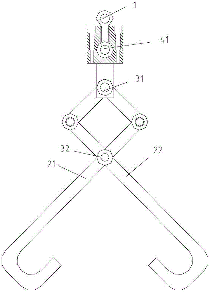
[0025] like Figure 1-2 As shown, the embodiment of the present invention provides a cylinder hoist, including a hoist ring 1, a grabbing device, and a clamping device. The suspension ring 1 is arranged above the grabbing device through the cross bar 41 to provide a lifting point for the hanging grabbing device.

[0026] The grabbing device includes a left ratchet and a right ratchet, and the left ratchet and the right ratchet are arranged symmetrically at both ends of the clamping device. Each pawl includes a front pawl arm 21 and a rear paw arm 22, the front pawl arm 21 and the rear pawl arm 22 are hinged to each other in a cross shape, and the lower ends of the front paw arm 21 and the rear pawl arm 22 are bent to form a clamping portion.

[0027] The clamping device includes a first pull rod 31, a second pull rod 32, a first connecting rod 33, and a second conn...


PUM


Abstract

The invention discloses a lifting appliance for a cylinder. The lifting appliance comprises a lifting ring, a cross rod and a grabbing device. The lifting ring is arranged above the grabbing device through the cross rod, and a lifting point position is provided for lifting of the grabbing device. The lifting appliance is characterized in that the lifting appliance further comprises a clamping device; the grabbing device comprises a left pawl and a right pawl, and the left pawl and the right pawl are symmetrically arranged at the two ends of the clamping device; each pawl comprises a front pawl arm and a rear pawl arm, wherein the front pawl arm and the rear pawl arm are hinged to each other and are in a crossing shape, and the lower end of the front pawl arm and the lower end of the rear pawl arm are bent oppositely to form a clamping part; and the clamping device is used for adjusting the distance between the clamping parts in the front pawl arms and the rear pawl arms. The lifting appliance has the beneficial effects that the lifting appliance is simple, easy to operate and stable in lifting process, the quality problem caused by premature wear of a spindle cover is avoided through lifting under fixing of the pawls, and the lifting appliance can be suitable for multiple machine types.

Description

technical field [0001] The invention relates to the technical field of hangers, in particular to a cylinder hanger. Background technique [0002] Cylinder block sling is an auxiliary tool for hoisting the cylinder block when assembling the engine. For example, the hoisting of the engine body on the line and off the line requires the use of the sling. The traditional cylinder hoist is generally a simple hook, which needs to be manually righted to ensure the stability of the cylinder during hoisting. The hoisting process has the disadvantages of being unstable and easy to fall, which is likely to cause safety accidents, and the joint surface between the hook and the main shaft cover during the hoisting process The contact causes early wear of the lower main shaft cover, which affects the performance of the diesel engine. Contents of the invention [0003] Aiming at the deficiencies of the prior art, the present invention provides a simple and easy-to-operate hoisting device...

Claims


Application Information

Patent Timeline
IPC IPC(8): B66C1/58
Inventor 王可喜唐来明
Owner ANHUI QUANCHAI ENGINE
Why Eureka
Eureka Blog
Learn More