Fluorescent lamp testing device

A technology of fluorescent lamps and photodiodes, applied in the direction of measuring devices, lamp testing, measuring electricity, etc., to achieve the effect of preventing damage

Inactive Publication Date: 2016-01-27
弗兰克公司
View PDF6 Cites 0 Cited by
  • Summary
  • Abstract
  • Description
  • Claims
  • Application Information

AI Technical Summary

Problems solved by technology

However, this discriminator device does not provide any other electrical test for fluorescent lamps and lighting fixtures

Method used


Image

  • Fluorescent lamp testing device
  • Fluorescent lamp testing device
  • Fluorescent lamp testing device

Examples


Embodiment Construction

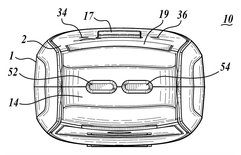
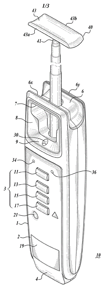
[0019] go to figure 1 , which shows an apparatus 10 for testing fluorescent lamps and lighting fixtures. The device has an elongated rectangular body 1 with two relatively short ends 4, 6 opposite each other. The rectangular body has an elongated surface 2 disposed between opposite short ends 4, 6 of the body 1 . The elongated surface 2 includes a control panel 3 . The control panel 3 includes a number of operator input buttons: button 21 turns the device 10 on or off; button 11 initiates a test for identifying ballast type; button 13 initiates a test for gas integrity; A test of the ballast's operability; and button 17 initiates a non-contact voltage test to determine if AC line voltage is available to the lighting fixture. Indicator lights 34, 36 respectively indicate whether the ballast under test is a magnetic ballast or an electronic ballast. On the short end 4 of the body 1 are pin receiving terminals 52, 53 for testing the filament conductivity. see figure 2 with...


PUM


Abstract

A fluorescent lamp testing device 10 has a microcontroller 100 that controls tests for ballast discrimination as well as gas integrity, ballast operation, filament continuity and line voltage. The ballast discrimination test is performed by the microcontroller 100 in combination with a photodiode 30 and high / low pass filter 32. Gas integrity is tested with pulse width modulation and a high-voltage, step-up transformer (PWM / T) circuit 42 and an antenna 40. A built-in continuity tester has input pins 52, 54 to test the continuity of the filaments in the fluorescent lamp 12. The antenna 40 and a voltage-divider / voltage-sensor connected to the secondary coil in the transformer test for ballast operation. A PCB conductive loop 18, rectifier 20 and op amp 22 test for line voltage.

Description

Background technique [0001] Fluorescent lighting is ubiquitous in industrial, commercial and residential installations. Studies have shown that fluorescent lights produce light more efficiently than incandescent lights. Recent changes in federal law requiring increased efficiency for all lamps will likely lead to higher production and use of fluorescent lamps. However, fluorescent lamps have certain disadvantages. Other studies have shown that fluorescent lights with low-frequency magnetic ballasts produce flicker, which may induce migraines. Such lights can also create the beat frequency associated with computer monitors, which can also trigger migraines. Conventional magnetic ballasts can be insulated with PCB material, which is toxic to humans. Because of the aforementioned potential and actual health hazards of fluorescent lamps with magnetic ballasts, regulatory agencies are now restricting fluorescent fixtures with magnetic ballasts to outdoor use only. It is mandat...

Claims


Application Information

Patent Timeline
Patent Type & Authority Applications(China)
IPC IPC(8): G01R31/44G01R31/00
CPCG01R31/245G01R31/44
Inventor M.B.马琴斯基R.罗德里格斯
Owner 弗兰克公司
Why Eureka
Try Eureka