Aero-engine simulation test bed on the basis of birotor simplified dynamic model design

An aero-engine and dynamic model technology, applied in simulators, instruments, control/regulation systems, etc., can solve the problems of complex model structure, low efficiency of quantitative analysis and calculation, and difficult to achieve qualitative analysis.

Inactive Publication Date: 2016-01-27
HARBIN INST OF TECH
View PDF2 Cites 19 Cited by
  • Summary
  • Abstract
  • Description
  • Claims
  • Application Information

AI Technical Summary

Problems solved by technology

The model structure established by finite element software is complex and suitable for quantitative calculation of linear vibration characteristics, but the calculation efficiency of quantitative analysis for nonlinear problems is low, and qualitative analysis is difficult to achieve

Method used


Image

  • Aero-engine simulation test bed on the basis of birotor simplified dynamic model design
  • Aero-engine simulation test bed on the basis of birotor simplified dynamic model design
  • Aero-engine simulation test bed on the basis of birotor simplified dynamic model design

Examples


Embodiment 1

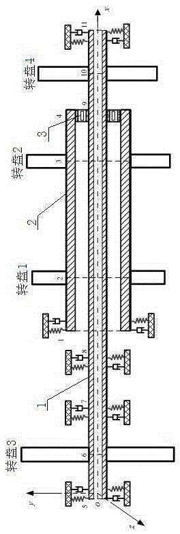
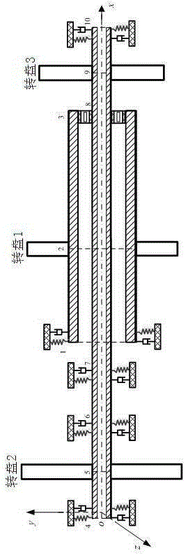
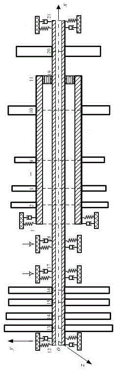
[0069] A kind of aero-engine simulation test-bed based on double-rotor simplified dynamics model design, its composition comprises: test-bed frame, described frame adopts the structure supporting low-pressure rotating shaft 1 of 6-point support and the high-pressure rotating shaft that is sleeved on the outside of low-pressure rotating shaft 2;

[0070] The dual-rotor system of an aero-engine adopts a 6-point support structure, in which the high-pressure rotor system adopts a two-point structure and adopts a 1-0-1 support method; the low-pressure rotor system adopts a four-point structure and adopts a 1-2-1 support method; The bearing supports in the dual-rotor system are numbered 1-6 from left to right, and bearing 5 is the intermediate bearing 3. According to the support structure and working principle of the aero-engine dual-rotor system, a relatively accurate complex dynamic discrete model ModelA of the aero-engine dual-rotor system with a 6-point support structure is esta...

Embodiment 2

[0106] According to the aero-engine simulation test-bed designed based on the dual-rotor simplified dynamic model described in Example 1, the critical speeds of the three models and the relative errors between the simplified model and the complex model under different elastic support coefficients. The support is an isotropic elastic support. In this paper, the dual-rotor system model is discretely modeled and simplified. Here, it can be assumed that all supports have the same stiffness, and the elastic support coefficient is 1*10 4 N / m changes to 2*10 for approximately rigid support 9 N / m. representing different models i order critical speed, where ,Model B and model C First i order critical speed with respect to the model A No. i critical speed error Expressed as

[0107] (11)

[0108] Figure 4 to Figure 11 When the system rotates in the same direction and the high-voltage rotor is the main excitation, the comparative analysis diagrams of the first four criti...


PUM


Abstract

The present invention provides an aero-engine simulation test bed on the basis of a birotor simplified dynamic model design. A rotor system is the core structure of an aircraft engine, and the birotor structure is the main structure employed by the modern aircraft engine. The aero-engine simulation test bed comprises a test bed frame, and the frame is configured to support a low pressure rotating shaft (1) and a high pressure rotating shaft (2) sleeved at the outside of the low pressure rotating shaft through a 6-piont supporting structure; the high pressure rotating shaft is supported through adoption of a 1-0-1 bearing distribution mode, and the low pressure rotating shaft is supported through adoption of 1-2-1 bearing distribution mode; and the bearing of connecting one end of the high pressure rotating shaft with the low pressure rotating shaft is an inter-shaft bearing (3). For the design of the rotors of the model, a complex discrete dynamic model with multiple wheel discs is established through adoption of the finite element method, and then the model is simplified based on the centroid concentration method. The present invention is used for an aero-engine simulation test bed on the basis of a birotor simplified dynamic model design.

Description

Technical field: [0001] The invention relates to an aeroengine simulation test bench designed based on a double-rotor simplified dynamics model, which is especially applied to the aeroengine simulation test of an aeroengine rotor without a rotary disc. Background technique: [0002] The rotor system is the core structure of an aero-engine, and the dual-rotor structure is the main structural form adopted by modern aero-engines, which refers to the structure in which the high-pressure rotor and the low-pressure rotor are connected together through intermediary bearings. The study of the dynamic characteristics of the aero-engine dual-rotor system is inseparable from a reasonably simplified dynamic model. Chen Yushu et al.[1] reviewed and looked forward to the dynamics of the aero-engine, and pointed out that a suitable simplified model should be established for the structure and working characteristics of the aero-engine, and the regularity of some important parameters on the ...

Claims


Application Information

Patent Timeline
Patent Type & Authority Applications(China)
IPC IPC(8): G05B17/02
Inventor 侯磊路振勇孙传宗靳玉林陈予恕
Owner HARBIN INST OF TECH
Why Eureka
Try Eureka