Orthopaedic traction frame

A technology of orthopedic traction frame and box, which is applied in the fields of fracture and medical science, and can solve the problems of poor stability of the traction frame

Inactive Publication Date: 2016-02-03
李涛
View PDF8 Cites 3 Cited by
  • Summary
  • Abstract
  • Description
  • Claims
  • Application Information

AI Technical Summary

Problems solved by technology

[0005] Aiming at the deficiencies of the prior art, the present invention discloses an orthoped

Method used


Image

  • Orthopaedic traction frame
  • Orthopaedic traction frame
  • Orthopaedic traction frame

Examples


Embodiment Construction

[0018] In order to make the purpose, technical solutions and advantages of the embodiments of the present invention clearer, the technical solutions in the embodiments of the present invention will be clearly and completely described below in conjunction with the drawings in the embodiments of the present invention. Obviously, the described embodiments It is a part of embodiments of the present invention, but not all embodiments. Based on the embodiments of the present invention, all other embodiments obtained by persons of ordinary skill in the art without creative efforts fall within the protection scope of the present invention.

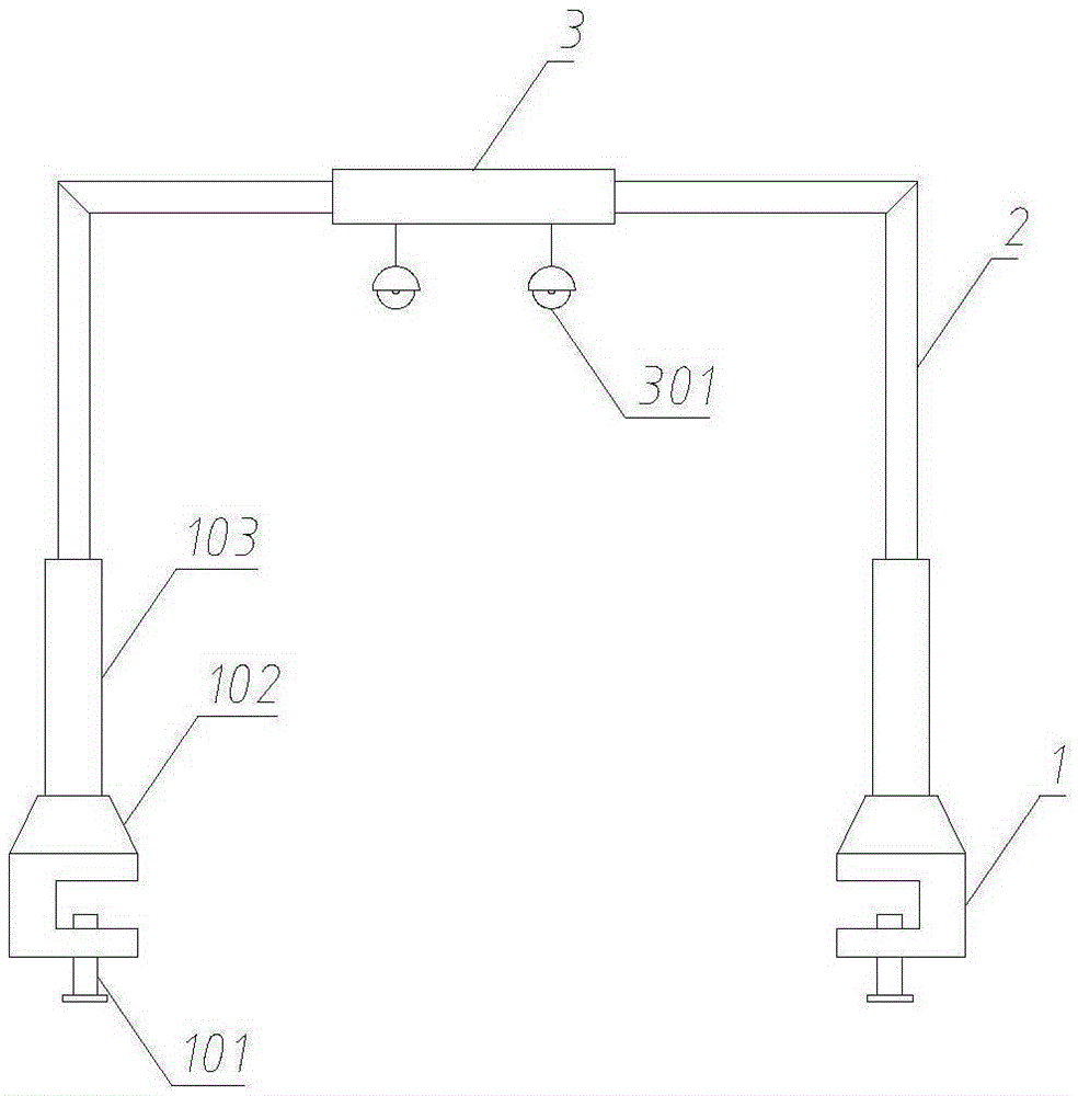
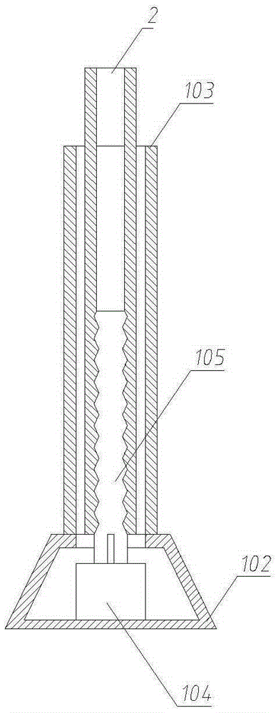
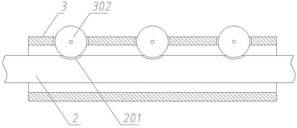
[0019] Such as Figure 1 to Figure 3 As shown, the orthopedic traction frame described in the embodiment of the present invention includes a foot, a bracket and a sleeve, the foot includes a fixing screw, a motor box, a hollow column, a motor and a rotating shaft, and the fixing screw is arranged on the The lower end of the box; the hollow column...


PUM


Abstract

The invention discloses an orthopaedic traction frame and relates to the technical field of medical equipment. The orthopaedic traction frame comprises foot bases, a support and a sleeve. The foot bases comprise fixing screws, motor boxes, hollow upright columns, motors and rotary shafts. The fixing screws are arranged at the lower ends of the motor boxes. The hollow upright columns are arranged at the upper end of the motor boxes and communicated with the motor boxes. The motors are arranged in the motor boxes and connected with the rotary shafts. The rotary shafts are connected with the support. The height of the support can be automatically increased through cooperation of the motors and the rotary shafts in the foot bases and the support. By means of arrangement of rolling wheels and corresponding grooves, the sleeve can be quickly positioned.

Description

technical field [0001] The invention relates to the technical field of medical equipment, in particular to an orthopedic traction frame. Background technique [0002] As we all know, the traction bed is a novel device that uses mechanical transmission to perform traction. It is widely used for lumbar disc herniation, lumbago, radioactive numbness of legs and feet, and walking caused by various acute and chronic injuries. Leg and foot muscle atrophy caused by weakness, as well as symptoms such as traumatic cervical spine fractures, dislocations, and dislocations; it can also be applied to clinical symptoms such as cervical spine dizziness, headache, tinnitus, and abnormal blood pressure. [0003] At present, the general traction frame is adjusted and arranged on the head or tail of the bed frame through the connector, and a pulley that can rotate around its own axis is set on the traction frame. One end of the traction rope acts on the place where the human body needs to be t...

Claims


Application Information

Patent Timeline
IPC IPC(8): A61F5/042
Inventor 李涛
Owner 李涛
Why Eureka
Try Eureka