Waterflow energy generator

A generator and water flow technology, applied in hydroelectric power generation, renewable energy power generation, engine components, etc., can solve problems such as abnormal operation, high requirements for dam height and water storage capacity, and long construction period

Inactive Publication Date: 2009-12-23
SHAANXI NORMAL UNIV
View PDF0 Cites 12 Cited by
  • Summary
  • Abstract
  • Description
  • Claims
  • Application Information

AI Technical Summary

Problems solved by technology

Traditional hydropower stations need to rely on river channels and landforms to block rivers and build dams. Building dams requires a large investment and a long construction period, which affects the ecological balance of the upstream and downstream and the safety of the surrounding living environment, and causes a large number of immigration problems. This is why traditional hydroelectric power stations cannot be built anywhere on rivers
[0003] The existing wheeled hydroelectric generator patent uses a single row of flat spokes, the resistance of the water is large, the speed is unstable, and the water wheel is fixed at a certain height, so it cannot operate normally in the dry season and flood season

Method used


Image

  • Waterflow energy generator
  • Waterflow energy generator
  • Waterflow energy generator

Examples


Embodiment 1

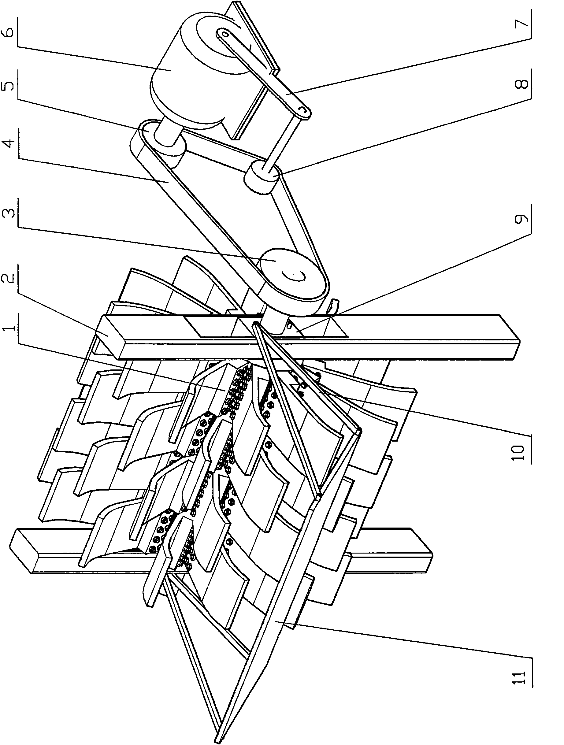
[0019] exist figure 1 , 2 , 3, the water flow energy generator 6 of the present embodiment consists of water wheel 1, column 2, driving pulley 3, belt 4, driven pulley 5, generator 6, adjusting wheel frame 7, adjusting wheel 8, slide block 9, The connecting rod 10 and the energy-gathering deflector 11 are connected to form.

[0020] The two columns 2 are processed with track grooves along the length direction, and a slider 9 is installed in each of the track grooves of the two columns 2. Track grooves are processed on both sides of the slider 9, and the slider 9 can be placed in the track groove of the column 2. Move up and down, the central position of slide block 9 is equipped with waterwheel 1, promptly moves up and down on column 2 with respect to waterwheel 1.

[0021] The left and right ends of the energy-gathering deflector 11 are fixedly installed on the slider 9 of the column 2 with two connecting rods 10 and threaded fastening joints respectively. The shape of the ...

Embodiment 2

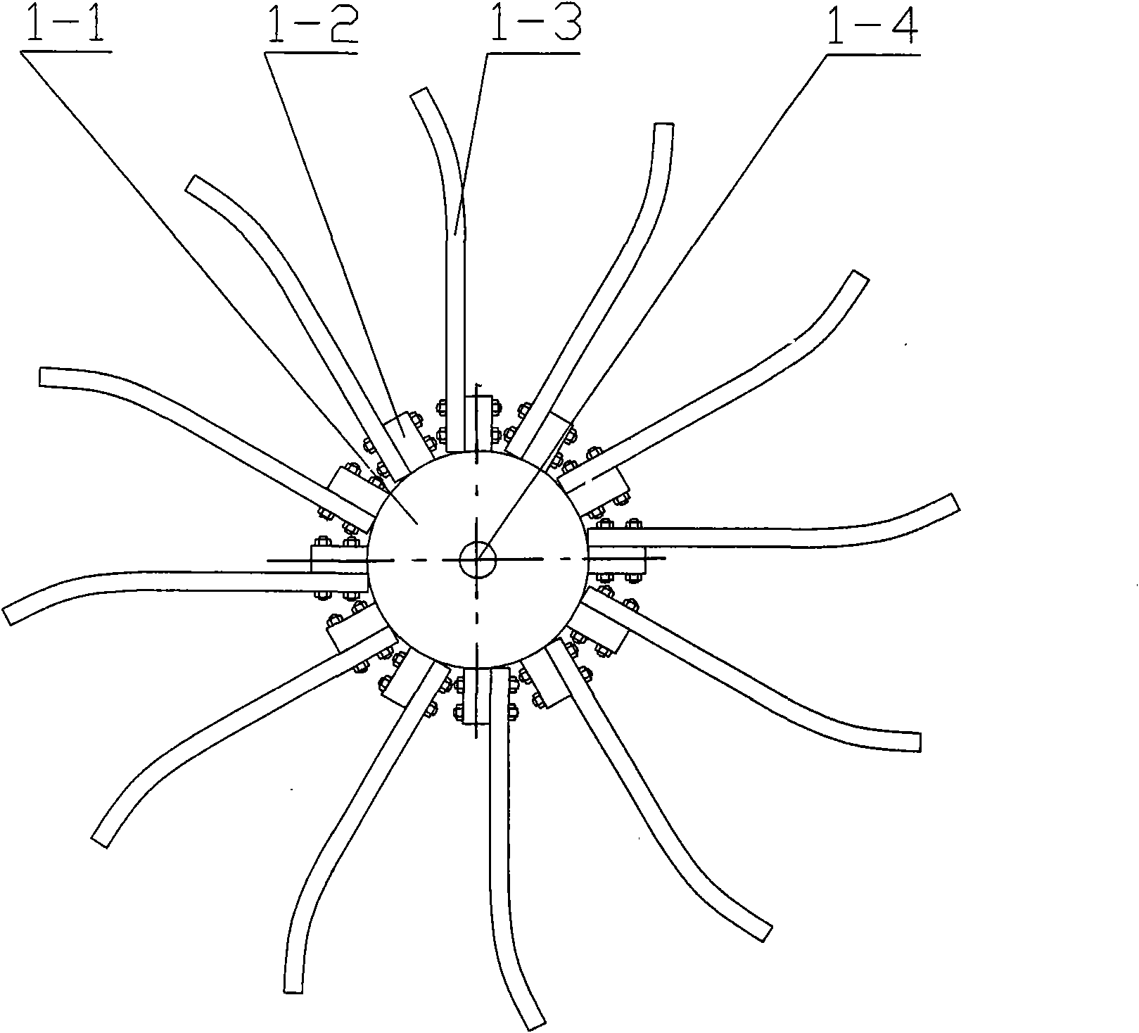
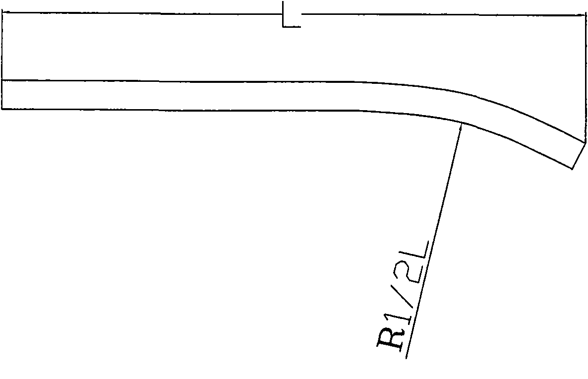
[0024] In this embodiment, the circumference of the outer surface of the buoy 1-1 of the water wheel 1 is fixedly connected with four sets of hubs 1-2 with threaded fastening connectors, and one set of hubs 1-2 is in diameter with the adjacent set of hubs 1-2. Arranged in a staggered direction, each group has 12 radially arranged hubs 1-2 parallel to the axis, and one blade 1-3 is fixedly connected to each hub 1-2 with a threaded fastening connector, and the blade 1 The shape of -3 is a curved plate whose outer end is an arc, and the radius R of the arc is 2 / 5 of the total length of the blades 1-3. Other components and the coupling relationship of the components are the same as in Embodiment 1.

Embodiment 3

[0026] In this embodiment, the circumference of the outer surface of the buoy 1-1 of the water wheel 1 is fixedly connected with four sets of hubs 1-2 with threaded fastening connectors, and one set of hubs 1-2 is in diameter with the adjacent set of hubs 1-2. Arranged in a staggered direction, each group has 12 radially arranged hubs 1-2 parallel to the axis, and one blade 1-3 is fixedly connected to each hub 1-2 with a threaded fastening connector, and the blade 1 The outer end of -3 is arc-shaped, and the radius R of the arc is 3 / 5 of the total length of the blades 1-3. The other parts of the water wheel 1 and the connection relationship of the parts are the same as in the first embodiment. Other components and the coupling relationship of the components are the same as in Embodiment 1.


PUM


Abstract

The invention relates to a waterflow energy generator. Rails provided with slide blocks are arranged on two upright posts. The slide blocks can move along the rails up and down. A water wheel is arranged on the slide blocks, is provided with an energy-collecting flow guide plate connected with the slide blocks through a connecting rod and is connected with a generator through a driving mechanism. The invention adopts a water turbine, the water wheel can float on the water surface along with the water level, and the water turbine can rotate by the kinetic energy and the potential energy of the water, so the generator is driven to generate electricity, the height of the water turbine is automatically lifted according to the change of the water level of the river, the stability of the generator is increased, the flood discharge and the flood drainage are not affected, and the water blockage dam does not need to be constructed. The waterflow energy generator can be arranged on the watercourses of rivers and branches, arranged along the watercourse at intervals, and can be also arranged on the high-speed waterflow outlet position of the barrage hydropower stations.

Description

technical field [0001] The invention belongs to the technical field of hydroelectric power generation equipment, and in particular relates to a water current energy generator. Background technique [0002] The energy problem has become the main bottleneck restricting economic development. The current main energy that people rely on for survival - petrochemical energy is decreasing, which can no longer meet the needs of social and economic development. The environmental pollution caused by the extensive use of petrochemical energy has endangered the human society and the economy. Sustainable development has become an urgent global problem to be solved. The conflict between resources and sustainable economic development is intensifying. Hydropower generation, a pollution-free and clean power generation, is becoming more and more important in the national economy. The development of new energy and renewable energy has attracted great attention from all over the world. Compar...

Claims


Application Information

Patent Timeline
Patent Type & Authority Applications(China)
IPC IPC(8): F03B13/00F03B7/00F03B11/00
CPCY02E10/226Y02E10/223Y02E10/20
Inventor 胡文旭
Owner SHAANXI NORMAL UNIV
Why Eureka
Try Eureka