
A Method of Restraining Expansion Joint Diseases of Cable-supported Bridges

A technology of expansion joints and diseases, applied in bridges, bridge parts, bridge construction, etc., can solve the problems of insufficient bonding strength, easy damage, and difficult repair of concrete panels or beams, so as to reduce concrete cracking, increase durability, Enhance the effect of continuity

Active Publication Date: 2017-03-29
JSTI GRP CO LTD
View PDF5 Cites 0 Cited by
  • Summary
  • Abstract
  • Description
  • Claims
  • Application Information

AI Technical Summary

Problems solved by technology

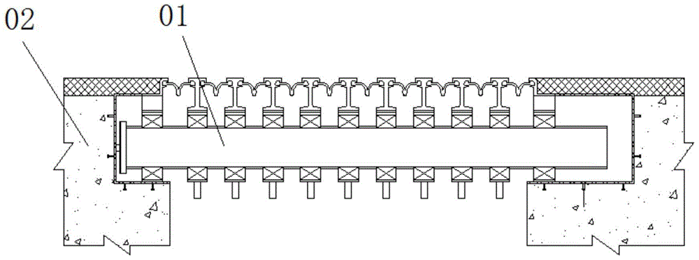
[0003] like figure 1 As shown, the expansion joint device 01 is directly fixed in the pre-opened groove at the end of the beam 02, without any damping equipment between the two, and there is no damping equipment between the beams. With the increase of traffic volume and vehicle load As the weight increases, the expansion joints of the bridge deck are set at the weak part of the beam end structure, directly bear the repeated impact of the wheel load, and are exposed to nature for a long time, and the environment is relatively harsh. Due to the wear and fatigue of the material, and the concrete Insufficient bond strength of panels or beams, easily damaged and difficult to repair

Method used


Image

  • A Method of Restraining Expansion Joint Diseases of Cable-supported Bridges
  • A Method of Restraining Expansion Joint Diseases of Cable-supported Bridges
  • A Method of Restraining Expansion Joint Diseases of Cable-supported Bridges

Examples


Embodiment Construction

[0023] In order to enable those skilled in the art to better understand the technical solutions in the present application, the technical solutions in the embodiments of the present application will be clearly and completely described below in conjunction with the drawings in the embodiments of the present application. Obviously, the described The embodiments are only some of the embodiments of the present application, but not all of them. Based on the embodiments in this application, all other embodiments obtained by persons of ordinary skill in the art without creative efforts shall fall within the scope of protection of this application.

[0024] The embodiments of the present invention are written in a progressive manner.

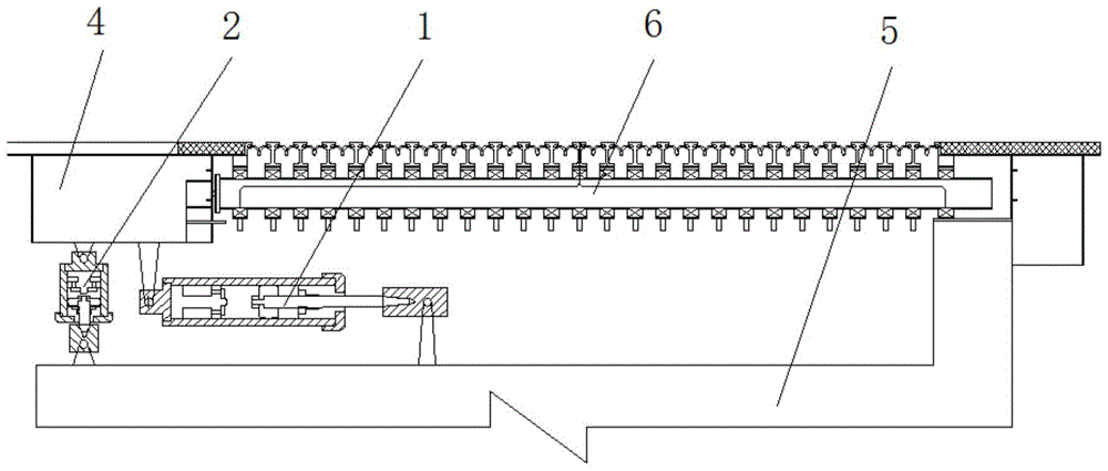
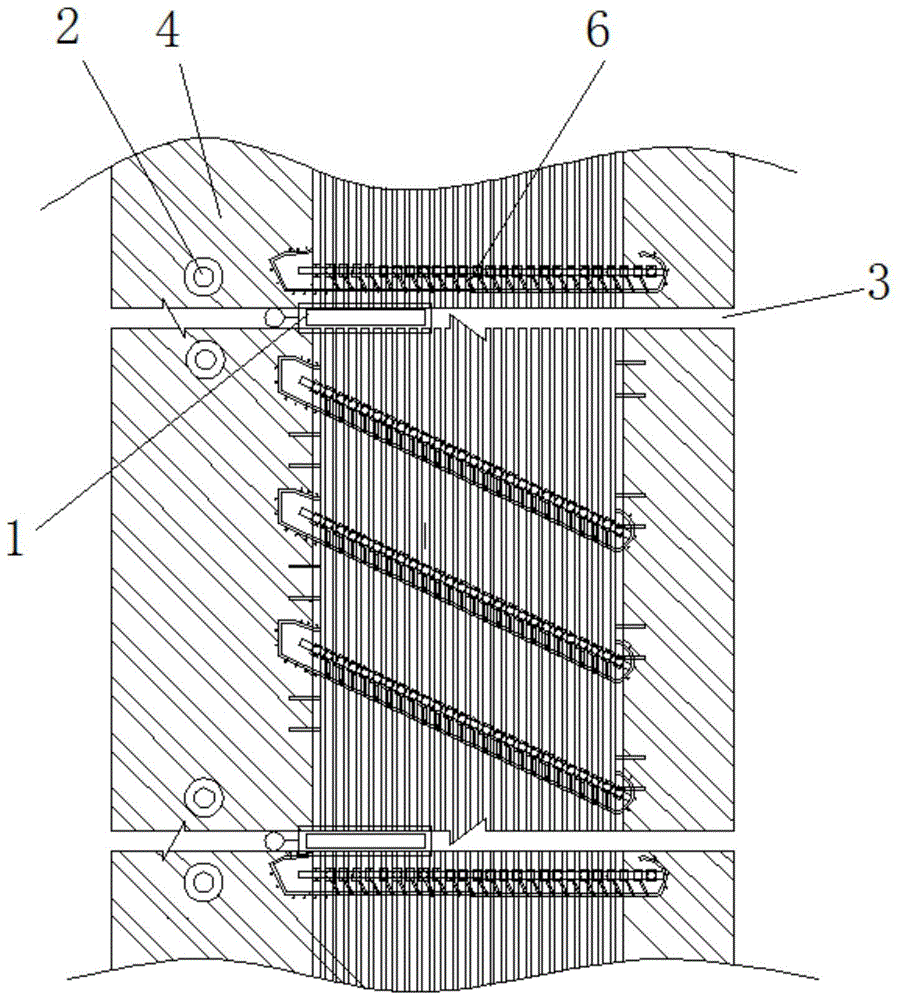
[0025] A device for suppressing damage to expansion joints of cable-supported bridges, comprising a longitudinal damping device 1 and a vertical damping device 2, the longitudinal damping device 1 is arranged parallel to the driving direction of the veh...


PUM


Abstract

The invention discloses a device and method capable of restraining the expansion joint disease of a cable-supported bridge. The device comprises longitudinal damping equipment and vertical damping equipment, the longitudinal damping equipment is arranged perpendicular to the traveling direction of vehicles, and the longitudinal damping equipment is parallel to an expansion joint and arranged under the expansion joint. One end of the longitudinal damping equipment is fixedly connected with the lower surfaces of two adjacent beam bodies beside the expansion joint together, and the other end of the longitudinal damping equipment is fixedly connected with the upper surface of a bridge pier located on the lower portion of the longitudinal damping equipment. The vertical damping equipment is perpendicularly arranged at the ends, close to the expansion joint, of the beam bodies, the upper portion of the vertical damping equipment is fixedly connected with the lower surfaces of the beam bodies, and the point of junction of the upper portion of the vertical damping equipment and the lower surfaces of the beam bodies is located on the outer side, relative to expansion joint equipment, of the longitudinal damping equipment. The expansion joint equipment is arranged in the traveling direction of the vehicles. The lower portion of the vertical damping equipment is fixedly connected with the upper surface of the bridge pier. At present, a vertical damper is arranged between the beam bodies and the bridge pier, hence, the vertical damping effect is improved, rotation of the expansion joint is restrained, and the durability of the expansion joint is improved.

Description

technical field [0001] The invention relates to the field of civil structures, in particular to a device and method for suppressing expansion joint diseases of cable-supported bridges. Background technique [0002] In the design of bridge structures, expansion joints are usually set between the ends of the two girders of the bridge, and between the end of the girder and the abutment. Its function is to adjust the displacement and connection between the superstructure caused by the characteristics of the vehicle load environment and the physical properties of the bridge construction materials. [0003] Such as figure 1 As shown, the expansion joint device 01 is directly fixed in the pre-opened groove at the end of the beam 02, without any damping equipment between the two, and there is no damping equipment between the beams. With the increase of traffic volume and vehicle load As the weight increases, the expansion joints of the bridge deck are set at the weak part of the b...

Claims


Application Information

Patent Timeline
Patent Type & Authority Patents(China)
IPC IPC(8): E01D19/00E01D19/06
Inventor 孙震徐剑张宇峰赵嗣辉
Owner JSTI GRP CO LTD
Learn More