Focus point detection of contact lenses and contact lenses capable of being tried on

A contact lens and focusing point technology, which is applied in glasses/protective glasses, glasses/goggles, optics, etc., can solve the problems of users wearing discomfort, prolonged time, and deviation of wearing contact lenses

Inactive Publication Date: 2016-02-03
嘉盛联合股份有限公司
View PDF4 Cites 3 Cited by
  • Summary
  • Abstract
  • Description
  • Claims
  • Application Information

AI Technical Summary

Problems solved by technology

[0003] However, before dispensing contact lenses for contact lens wearers, please refer to the Figure 4 , Figure 5 As shown, it is necessary to select try-in frame glasses that meet the corrected vision degree of the user. After confirming the corrected vision degree of the user, the contact lens A is made for wearing on the corneal surface of the user's eye. And the user is blinking so that the contact lens A can cover and stick to the surface of the cornea. However, at present, when the contact lens A is made, the focal point position B of the contact lens A is made at the exact center point (that is, the longitudinal axis and the horizontal axis The center of the intersection point of the axis) for the curvature of the contact lens A to extend from the center point to the outside to make a contact lens A with a fixed curvature, but because the eyeball, white of the eye and surrounding cornea of ​​each user's eye will There are curved surfaces with different radians. Not every user’s cornea has the same radian. Therefore, the position B of the eye focus point of different users will also be different, and it is not located at the center C of the second eye. If the contact lens The focus point position B of A is fixed at the center point position, which will cause the user to blink and adapt to contact lens A for a longer time when wearing contact lens A, and the focus point position B of contact lens A is adjusted to meet the After the curvature of the cornea of ​​the user's eyes, it is easy to cause contact lens A to not completely cover the center of the cornea, but to form a deviation, skew, etc., which ...

Method used


Image

  • Focus point detection of contact lenses and contact lenses capable of being tried on
  • Focus point detection of contact lenses and contact lenses capable of being tried on
  • Focus point detection of contact lenses and contact lenses capable of being tried on

Examples


Embodiment Construction

[0034] In order to achieve the above-mentioned purpose and effect, the technical means adopted in the present invention, its structure, and the method of implementation, etc., are hereby described in detail with respect to the preferred embodiments of the present invention. Its features and functions are as follows, so that it can be fully understood.

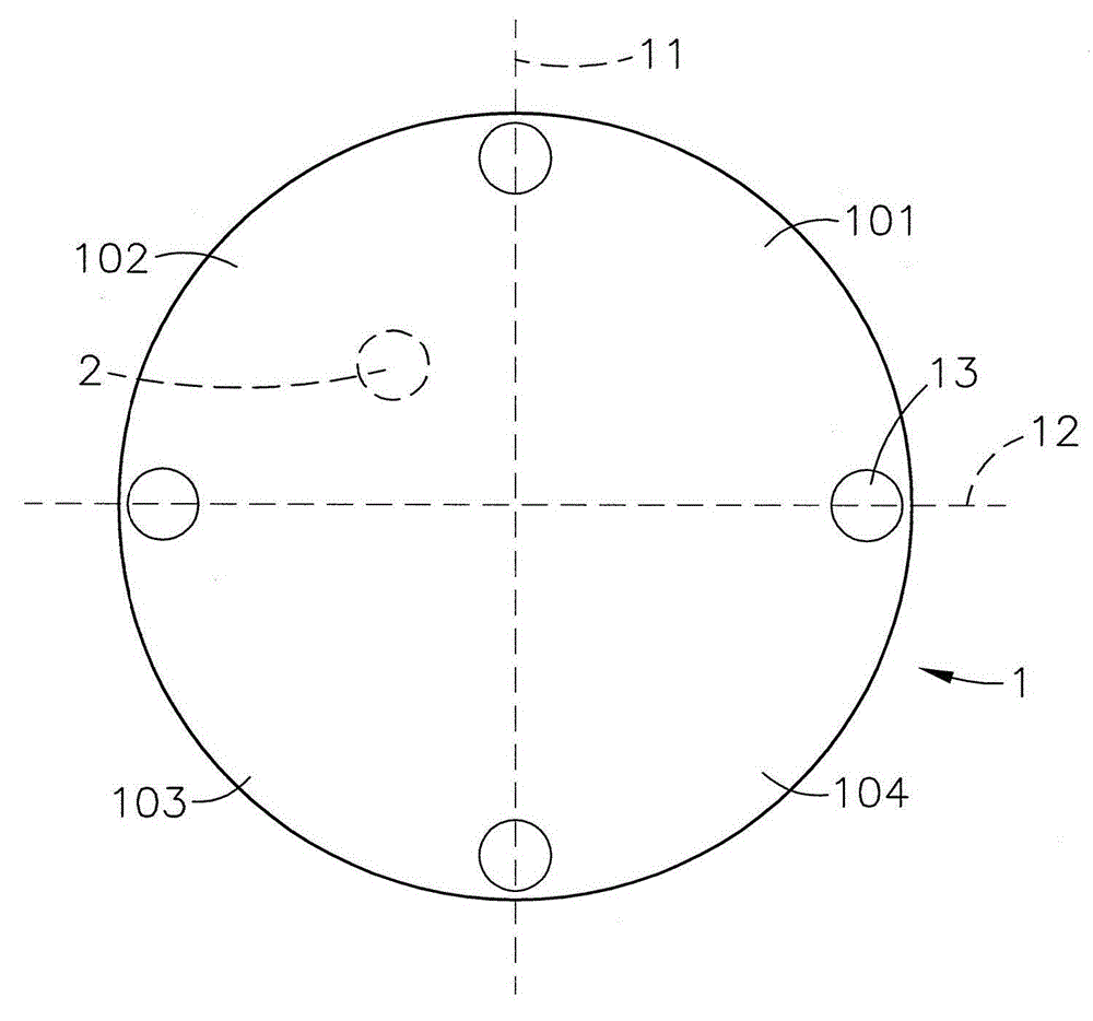
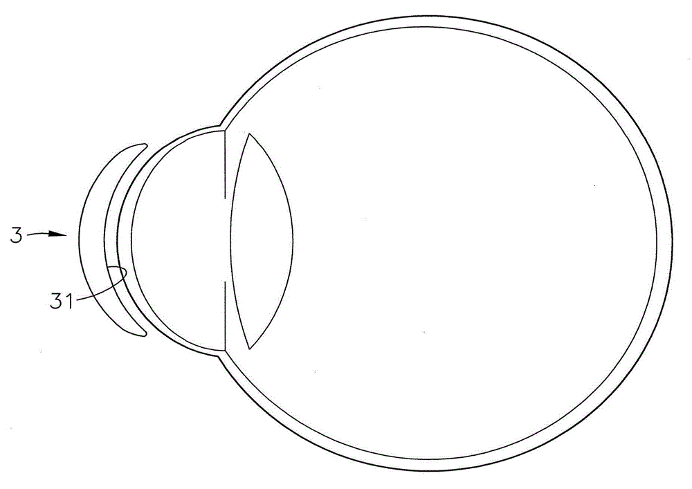
[0035] see figure 1 , figure 2 , image 3Shown, respectively is the detection step flow chart of the present invention, front plan view, side view, can clearly find out from shown in the figure, when the try-on contact lens 1 of the present invention is tested, the steps of its detection are:

[0036] (100) The contact lens 1 for try-in is fitted on the surface of the cornea of ​​the user's eye.

[0037] (101) The user adjusts the try-in contact lens 1 to cover the surface of the cornea by blinking, so as to adapt to the try-in contact lens 1 .

[0038] (102) A plurality of detection base points 13 are provided on the surf...


PUM


Abstract

The invention provides focus point detection of contact lenses and the contact lenses capable of being tried on. Detection steps are as follows: wearing the contact lenses capable of being tried on the surfaces of the corneas of a user, and adjusting the contact lenses to cover the surfaces of the corneas through blinking by the user, and to fit the surfaces of the corneas, generating focus points in any quadrant area between a longitudinal axis and a horizontal axis by virtue of the contact lenses capable of being tried on, marking, taking out the contact lenses capable of being tried on, preparing the contact lenses which are in proper radian change to the outer side from the focus points according to focus points marked on the surfaces of the contact lenses capable of being tried on so as to conform to the arc curved surfaces of the radian of the corneas of the eyes of the user who tries the contact lenses on and achieve the purpose of obtaining accurate focus point positions conforming to the eyes of the user.

Description

technical field [0001] The invention relates to a focus point detection of a contact lens and a contact lens for try-in, especially a contact lens that can be used for try-in to obtain a correct focus point. The base points are detected, and focus points are obtained in adjacent quadrants of each detection base point after the user tries them on, so as to achieve the purpose of making the contact lens conform to the correct focus point position of the user's eyes. Background technique [0002] With the research and development and innovation of various electronic and electrical products, it has brought many conveniences to people's daily life and work, especially the emergence of a large number of 3C electronic products has caused the popularization of applications in communications and the Internet, resulting in many People are immersed in the use of 3C electronic products, and use 3C electronic products in large quantities for a long time. Whether they are office workers, ...

Claims


Application Information

Patent Timeline
IPC IPC(8): G02C13/00G02C7/04
Inventor 吴怡璁
Owner 嘉盛联合股份有限公司
Why Eureka
Try Eureka