Universal flow track system

a technology of flow track and storage system, applied in the direction of dismountable cabinets, transportation items, refuse gathering, etc., can solve the problems of ineffective rails, inability to properly support heavy loads, and inability to meet the needs of users, and achieve the effect of low profil

Inactive Publication Date: 2004-05-18
UNEX CONVEYING SYST
View PDF17 Cites 120 Cited by
  • Summary
  • Abstract
  • Description
  • Claims
  • Application Information

AI Technical Summary

Benefits of technology

In accordance with the present invention, there is provided a universal flow rack system that can be fixtured to almost any supporting frame of a storage system without tools. The flow rack system of the invention features a flow track which has a roller conveying surface. The flow track comprises two elongated side rails that rotatably support a series of periodic, elongated, spaced-apart rollers therebetween. The flow t

Problems solved by technology

These prior art, commonly used rails could never properly support heavy loads, even with heavy, mid-support bracing.
The rails were never practical, despite their low cost, which was essentially their only appeal.
Therefore, the economy that is originally perceived with this system is, in actuality, deceptive.
Their frequent replacement more than counterbalances any initial savings.
The above-mentioned flow track system, on the other hand, was well received by the industry, but four major disadvantages remained: (1) it required horizontal toothed retainer bars; (2) the retainer bars required mechanical attachment to the frame, which was both laboriously expensive and time consuming; (3) the flow track system had no facility to extend itself in dept

Method used


Image

  • Universal flow track system
  • Universal flow track system
  • Universal flow track system

Examples


Embodiment Construction

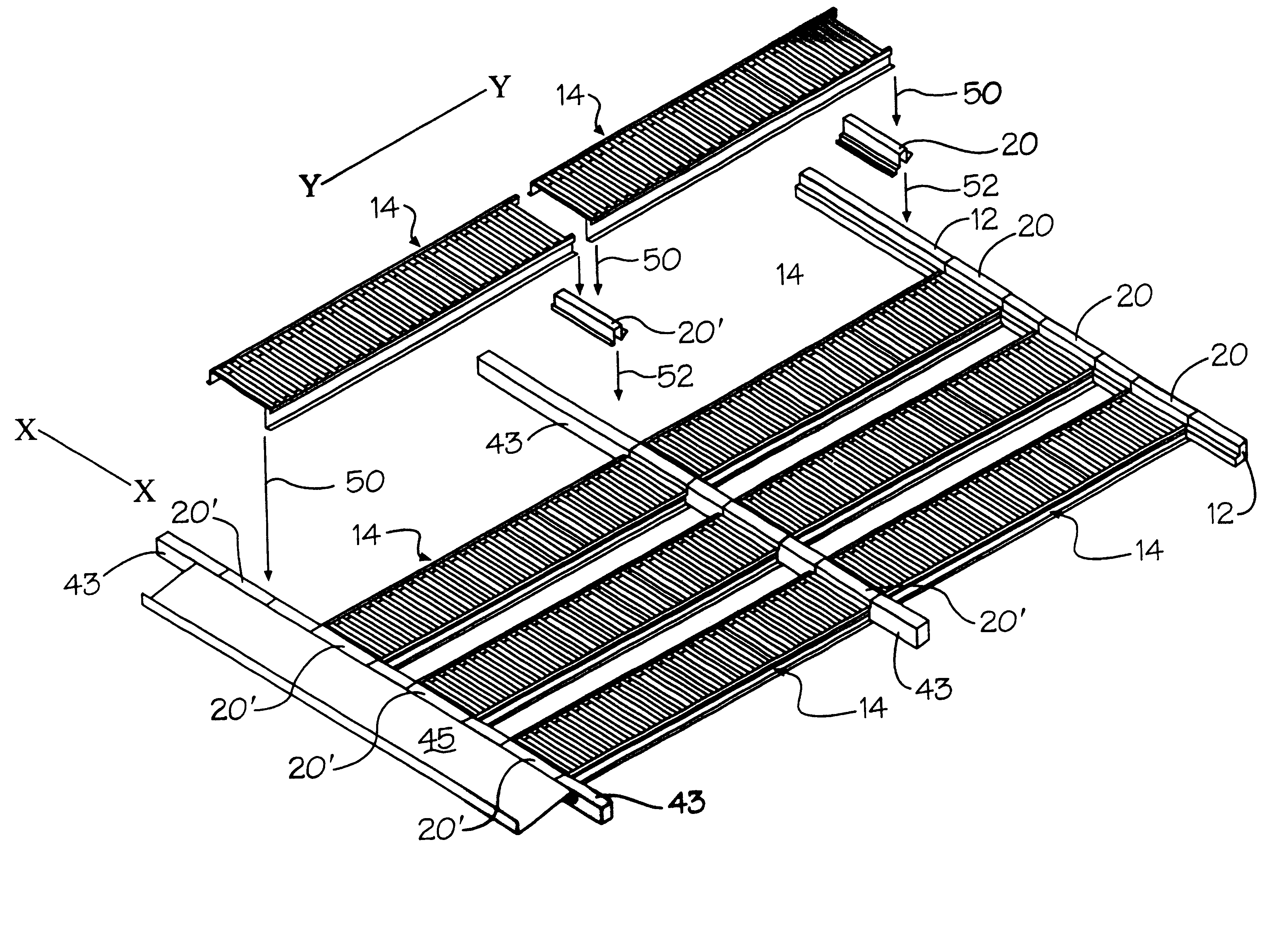
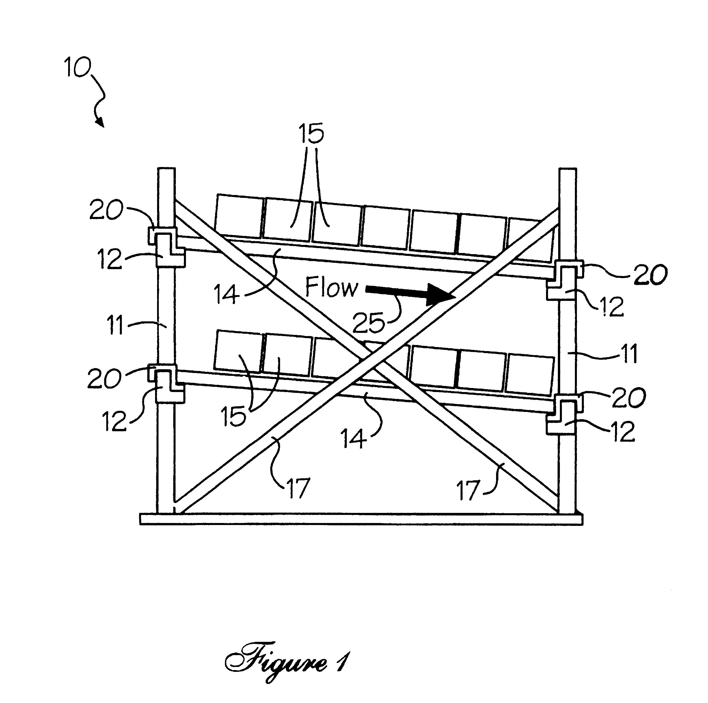
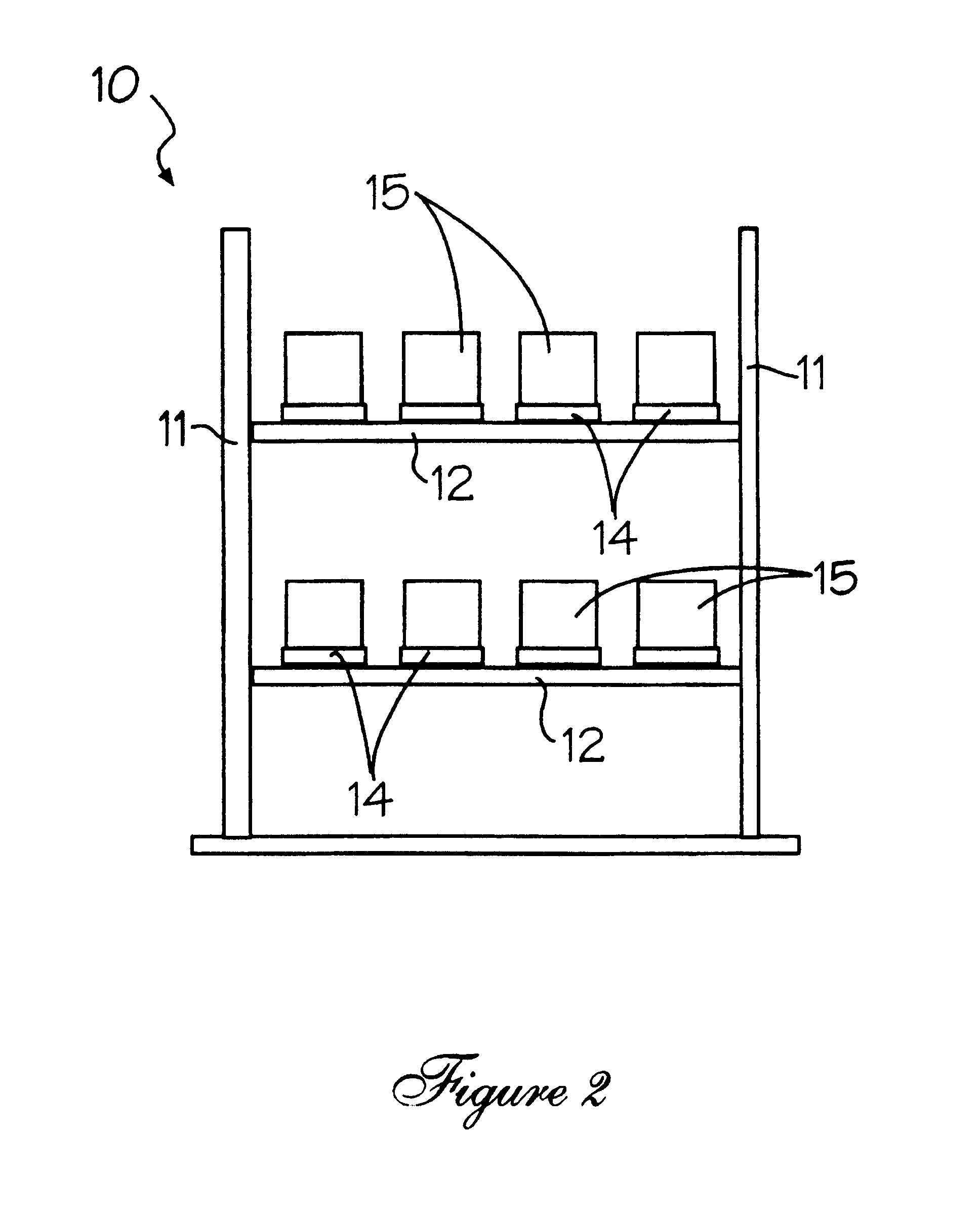
Generally speaking, the invention features a flow track comprising a plurality of periodically-spaced rollers, upon which materials can be conveyed from one position to another on the span. The rollers are rotatively supported between two rails or channels defining the flow track. The flow track is positionable between two end support beams of a storage frame or pallet rack, with each end support beam supporting a distal end of the flow track. The flow track is adjustably positionable along the entire horizontal length of the respective end support beams. A movable hanger member supports the flow track for adjustment about the end support beams, and is movable in a horizontal direction (along the X-axis or the longitudinal length of the support beams) with respect to the storage frame or pallet rack. An extended flow track system is achieved in the depth or material flow direction (Y-axis) by use of an alternate hanger member at mid-span. A front slide member is attachable to the fr...


PUM


Abstract

The present invention features a universal, low profile, expandable flow track system that can be drop-load mounted to almost any supporting frame or pallet rack. The flow track system of the invention features a flow track that mounts flush with its end supports, and is infinitely adjustable along both the horizontal axis and depth axis of the storage frame. The flow track is quickly assembled to, adjusted upon, and removed from, the storage frame.

Description

RELATED PATENTSThis application is related to U.S. Pat. No. 5,474,412, issued Dec. 12, 1995, for FLOW RACK SYSTEM.FIELD OF THE INVENTIONThe present invention pertains to material storage tracks and, more particularly, to an improved, extendable flow track storage system that is universally adaptable to, and infinitely adjustable about, most skeletal storage frames, with the aid of universal retaining elements.BACKGROUND OF THE INVENTIONThe above-identified U.S. Pat. No. 5,474,412 relates to a new flow track storage apparatus that is adjustable in all three orthogonal planes. The flow track component of the apparatus was designed to seat within a toothed retainer bar that mechanically mounts to the horizontal end supports of a warehouse pallet rack. The flow track is horizontally adjustable along the entire retainer bar and, hence, along the entire horizontal dimension of the pallet rack. This is accomplished by seating the flow track within particular retainer bar slots. The flow tr...

Claims


Application Information

Patent Timeline
IPC IPC(8): B65G13/00B65G1/02B65G13/12
CPCB65G1/023B65G13/12
Inventor PFEIFFER, HAROLDNEUWIRTH, FRANK J.
Owner UNEX CONVEYING SYST
Why Eureka
Try Eureka