Perhaps the most frightening aspect about the approaching energy crisis is that so few are aware of the seriousness of the problem and the devastating
impact that the worsening shortages of
oil and natural gas will have upon our industrialized society, upon our nation, and upon our lives.
Although turbines designed for the Gulf
Stream can also generate low-cost
electricity from the Kuroshio, they would probably not operate at quite the same high capacity factors in that current as they would in the Gulf
Stream.
Tidal currents are of interest—not because a tethered submersible power generator would be well suited for harvesting their
kinetic energy—but because they also involve the generation of electricity
underwater, the transmission of that power to
shore, and because serious money is being invested in their development, even though their capacity factors are very low.
A wind
turbine with many blades or very wide blades (turbines with a
solid rotor) would be subject to extremely large forces when the wind blows at hurricane velocities because the energy increases with the cube of its velocity.
Although the amount of heat from all the losses in large generators is only about one percent of the output, it can be numerically great.
However, because plastics do not have the same ability to transfer heat as do the
metal housings used on the wind turbines, and because there will be no outside source of air for cooling, some type of external cooling
system will be required to dissipate the heat produced by the generators and gearboxes.
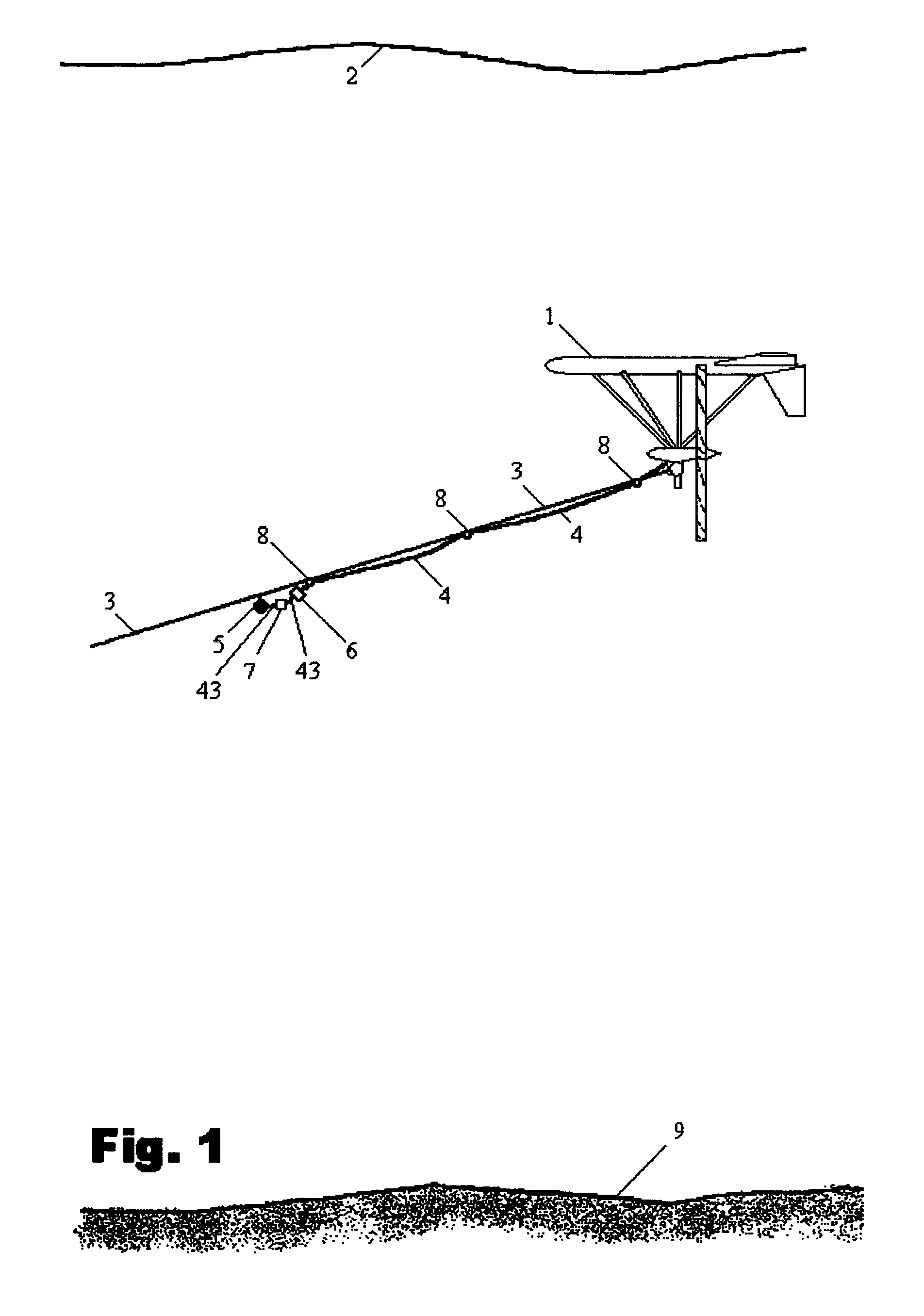
The problem with mounting the generating devices on platforms is that the strongest currents are located near the surface where the depths are usually greater than 1,200 feet and mounting the generating devices high above the ocean floor on giant structures would be extremely costly.
If the structures had shorter towers, the submersible power plants would be much more difficult to install and service and the turbines would be beneath the stronger current flow.
The problem with suspending the turbines from barges or pontoons is that they would interfere with ship traffic, be vulnerable to violent storms, and be unsightly.
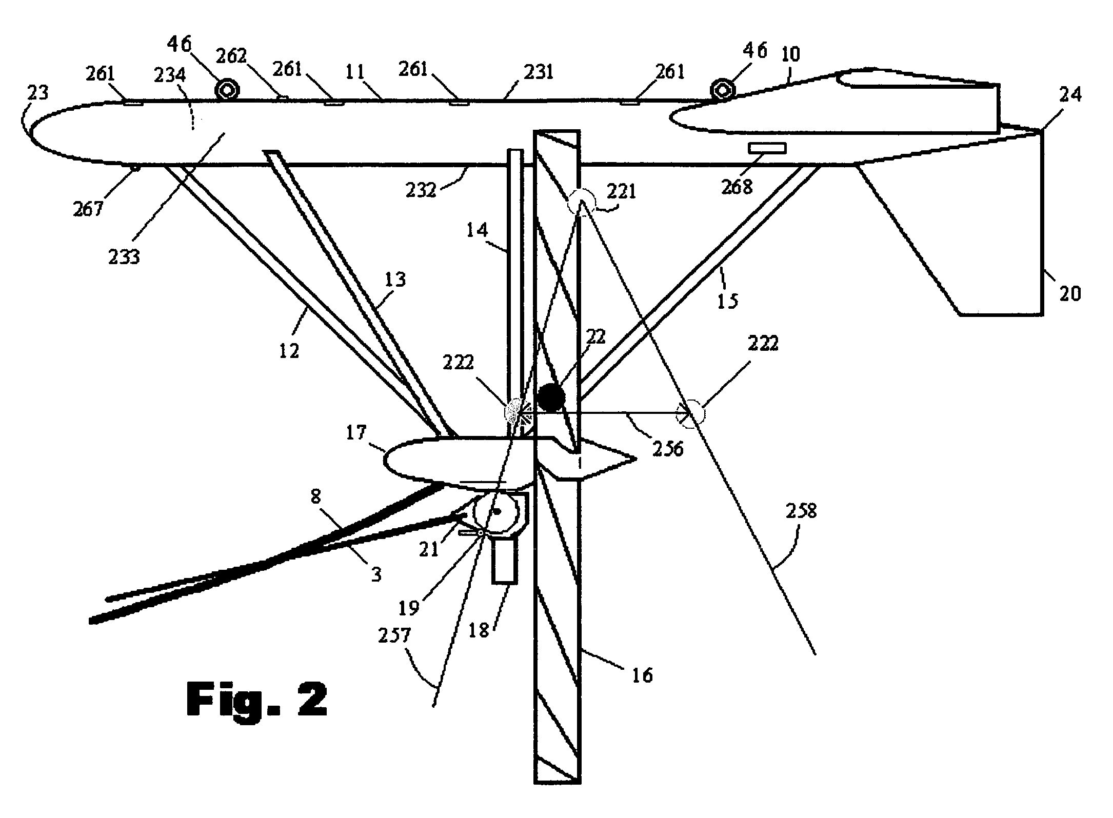
Also the lifting force provided by the hydrofoil that joins the nacelles is at the same level as the heavy elements, further adding to a lack of stability.
Because the anchor lines attach directly ahead of the center of drag, the canted wing tips would have little effect on stability.
With the attachment point located at the center of
buoyancy, if the device should have positive
buoyancy, the canted wing tips would decrease stability.
With the anchor attachment points being behind this “stabilizing fin,” the fin would make the device more unstable.
A problem with this approach is that, although the purpose of the generator is to capture kinetic energy to maximize
power output, it controls the depth by reducing that output.
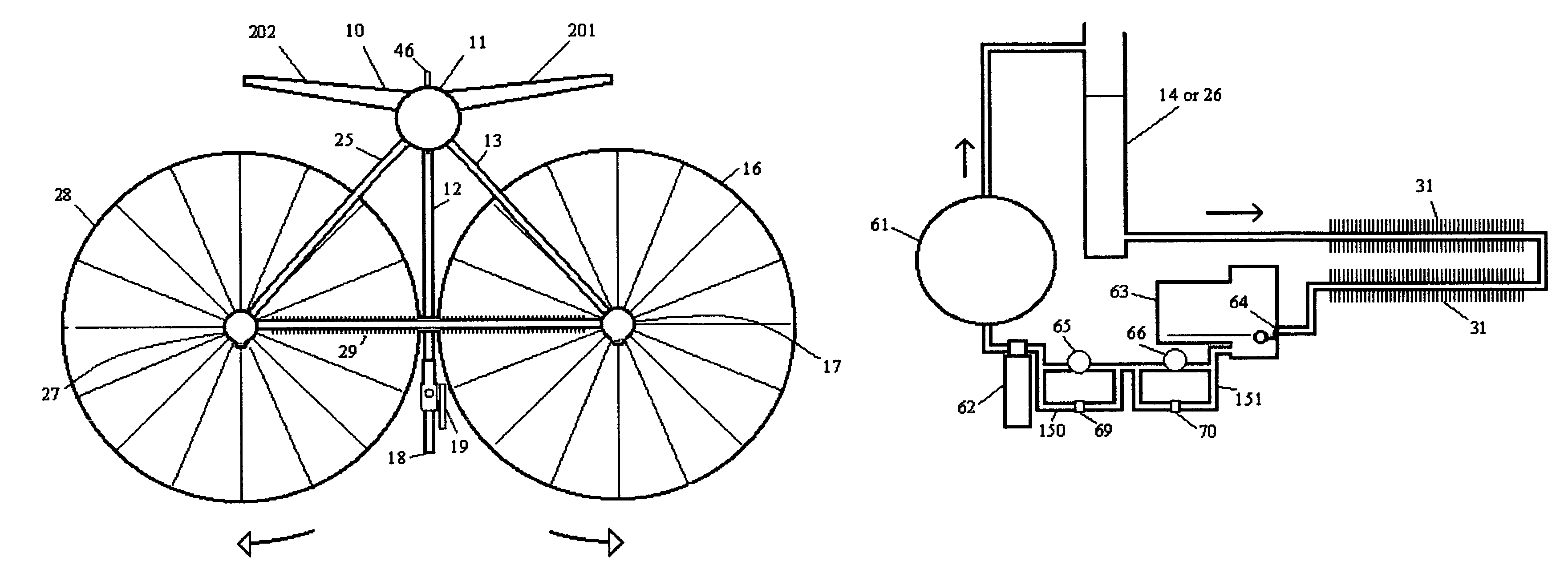
Although these are counter-rotating turbines are side-by-side, because they are mounted on vertical shafts, their
counter rotation has no effect on the device's stability.
In this and all other devices that use turbines mounted on vertical shafts—not only are the areas for capturing the energy of the moving fluid small in proportion to the frontal area of the device, they waste additional energy because—even though the fins on the reverse side of the vertical turbine may fold or open to allow water to have much less resistance as they rotate toward the front of the turbine—they still produce some drag that must be subtracted from the power produced by that side of the turbine that is being pushed by the kinetic energy of the flowing water.
The inefficiencies of all these vertical shafted turbines can be compared to using
paddle wheels for propelling boats rather than modern propellers, except they would be worse because the top blades of a boat's
paddle wheel meets far less resistance when moving forward through the air than would those blades of a vertical-shafted
water turbine blades moving against the much denser water.
Shrouds and Venturi-shaped tubes are not used on commercial wind-powered turbines because they do not increase the velocities enough to justify their cost.

