Screw conveyor to convey powdery material, in particular cement or the like

a conveyor and powdery material technology, applied in the direction of bulk conveyors, loading/unloading, packaging, etc., can solve the problems of increasing system efficiency, reducing the efficiency of the conveyor device, and not solving the problem, so as to achieve the effect of minimizing power was

Active Publication Date: 2020-09-01
WAMGRP
View PDF28 Cites 0 Cited by
  • Summary
  • Abstract
  • Description
  • Claims
  • Application Information

AI Technical Summary

Benefits of technology

[0026]The main aim of the present invention is therefore providing a screw conveyor to convey an aerated powdery material in which power waste is minimized by carefully designing the various screw portions in the screw conveyor, in particular by carefully selecting for each screw portion the law regulating the pitch variations of the points belonging to that particular screw portion.
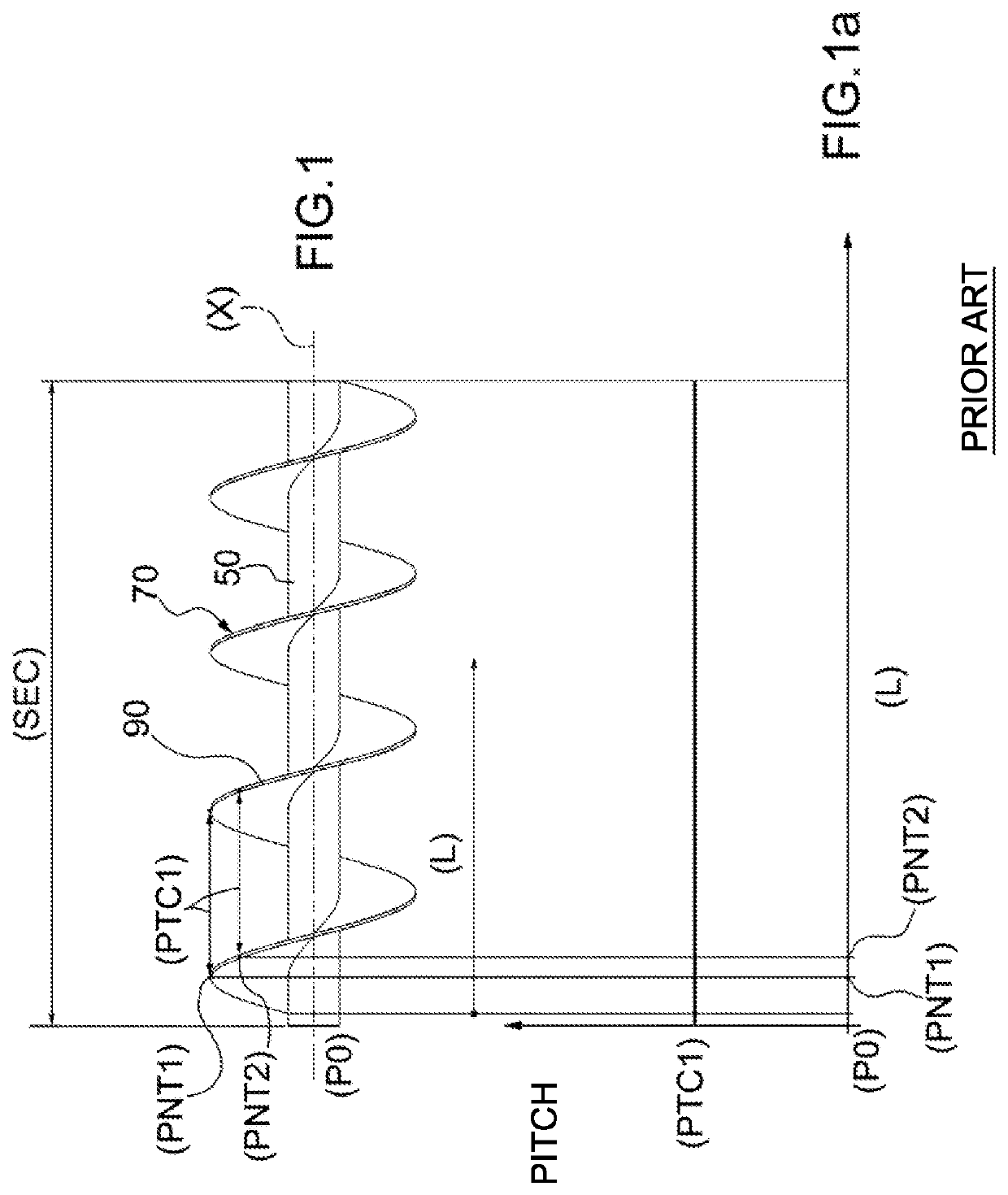
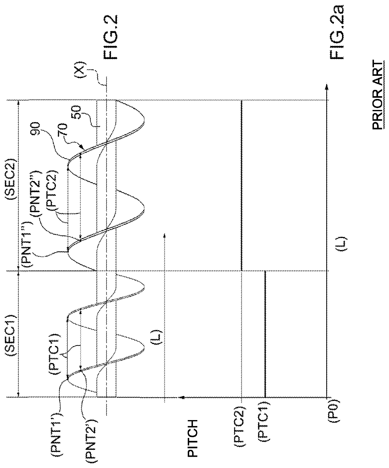
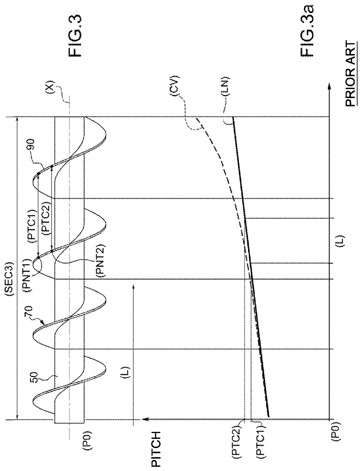
[0030]The gradual increase of the pitch of the points belonging to a same screw portion greatly reduces the advancement resistance of the material, because there are no longer agglomerated and compact fine particles that must slide on the screw to advance, but rather thin and rarefied fine particles that must instead be pushed.
[0032]In fact, the power of the quasi-fluid given by the intimate mixing of the particles with the gas (air, nitrogen, carbon dioxide, etc.) at the end of the “accelerating and launching screw portion” should easily overcome any intermediate, screwless support of the screw conveyor.
[0036]As previously mentioned, the siphoning of the fluidized material in a precise stretch of the screw conveyor can be avoided by reducing the pitch, thus creating a kind of “product accumulation” (essentially a kind of “plug” of material) to increase the filling level of the device.
[0037]It has been experimentally found that a variation of the pitch of the points within a given screw portion of the screw conveyor maximizes the transport efficiency and significantly reduces the amount of power consumed for the transport.

Problems solved by technology

However, it has been found that the efficiency of the system increases by limiting as much as possible the turbulence within the quasi-fluid.
In this regard, it has been experimentally found that the turbulence is directly proportional to the discrete jumps of the conveyor screw pitch; in this sense, also the welding of single screw stretches represents discrete jumps with a consequent loss of efficiency of the conveyor device.
However, in spite of some positive aspects, these solutions do not solve the problem of minimizing the power consumption to convey powdery material and maximizing the filling of the spires.
LTD) are sloping at a certain angle (e.g. to lift the powdery material from the ground to the floor of a building) they show a low efficiency (power loss) in conveying the powdery material.
However, the screw conveyor described in U.S. Pat. No. 3,056,487 (KIPPER) is not suitable for being installed in a complex plant to convey an aerated powdery material, e.g. a mixture of powdery cement and air (or any other suitable gas).
In particular, this screw conveyor is not suitable because it does not allow an optimal filling of the spires of the transfer screw during the filling step, on the one hand, and during the accelerating and launching step, on the other.

Method used


Image

  • Screw conveyor to convey powdery material, in particular cement or the like
  • Screw conveyor to convey powdery material, in particular cement or the like
  • Screw conveyor to convey powdery material, in particular cement or the like

Examples


first embodiment

[0069]FIG. 4 indicates with the reference number 100 as a whole a screw conveyor to convey a powdery material made according to the teaching of the present invention.

[0070]The screw conveyor 100 comprises a spiral blade 90 of a screw 70 wound around the central tube 50 and contained in an outer trough 80 provided with an inlet section 81 and an outlet section 82 of the fluidised powdery material; these sections are known with respect to the state of the art.

[0071]Incidentally, exactly at a loading mouth (HP) of the screw conveyor 100, there is a screw portion (ESEC) for the extraction of the powdery material, but it will not be analysed in detail in the present description because it is of a known type.

[0072]In use, the present screw conveyor 100 creates a suction depression.

[0073]The inlet section 81 is therefore the first cross section immediately after the hopper unloading mouth (HP).

[0074]The screw 70 is rotated by an electric motor (MT).

[0075]Constructively, the screw 70 made a...

second embodiment

[0089]the present invention shown in FIGS. 5, 5a, wherein the corresponding elements are indicated by the same numbers and symbols of FIGS. 4, 4a, shows the following different three screw portions 70 (other than the aforesaid extraction screw portion (ESEC), whose width substantially coincides with the width of the loading mouth (HP)):

[0090]a first portion of a transfer screw (TSEC) having a length (L2), substantially equal to the analogous first portion of FIGS. 4 and 4a;

[0091]a second accelerating and launching screw portion (LSEC), having a length (L3), substantially equal to the analogous second portion of FIGS. 4 and 4a; and

[0092]a third anti-siphon screw portion (ASEC) having a length (L4); the third anti-siphon screw portion (ASEC) being comprised between the first transfer screw portion (TSEC) and the second accelerating and launching screw portion (LSEC); the third anti-siphon screw portion (ASEC) having a continuously decreasing pitch, point by point, and a decreasingly ...


PUM


Abstract

A screw conveyor to convey powdery material, in particular cement. The screw conveyor comprises:a transfer screw; anda trough containing the transfer screw; the trough being provided with an inlet section and an outlet section of the powdery material.The screw conveyor is characterized in that the screw comprises:at least a first screw portion having a first law of continuous variation of the pitches of the screw, which can be graphically represented by means of a first function having in at least one stretch a first derivative other than zero; andat least a second screw portion having a second law of continuous variation of the pitches of the screw, which can be graphically represented by a second function having in at least one stretch a first derivative other than zero. The first law of continuous variation of the pitches is different from the second law of continuous variation of the pitches.

Description

CROSS-REFERENCE TO RELATED PATENT APPLICATIONS[0001]This application is a U.S. National Phase Application under 35 U.S.C. § 371 of International Patent Application No. PCT / IB2017 / 056026, filed Sep. 29, 2017, which claims the priority of Italian Application No. 102016000097907, filed Sep. 29, 2016, which is incorporated by reference as if expressly set forth in its entirety herein.TECHNICAL FIELD[0002]The present invention relates to a screw conveyor to convey a powdery material, in particular cement or the like.[0003]In fact, this screw conveyor is also suitable for conveying other quasi-fluid “sliding products”, which, in use, reach the screw conveyor when they have already been aerated, such as, e.g. cements, limes, fillers and the like.[0004]Therefore, what follows cannot be applied to materials such as sand and gravel, which are not sliding products in the aforementioned sense.BACKGROUND ART[0005]It is well known in the art that such sliding products (cements, limes, fillers, et...

Claims


Application Information

Patent Timeline
Patent Type & Authority Patents(United States)
IPC IPC(8): B65G53/48B65G33/26B65G33/14B65G65/46
CPCB65G33/14B65G33/265B65G33/26
Inventor MARCHESINI, VAINER
Owner WAMGRP
Why Eureka
Try Eureka