Layer 2 switch

a layer 2 switch and switch technology, applied in data switching networks, data switching details, multiplex communication, etc., can solve the problem that the layer 2 switch cannot perform multicast packet distribution together, and achieve the effect of reducing the amount of bandwidth wasted

Inactive Publication Date: 2008-08-26
HITACHI LTD
View PDF15 Cites 37 Cited by
  • Summary
  • Abstract
  • Description
  • Claims
  • Application Information

AI Technical Summary

Benefits of technology

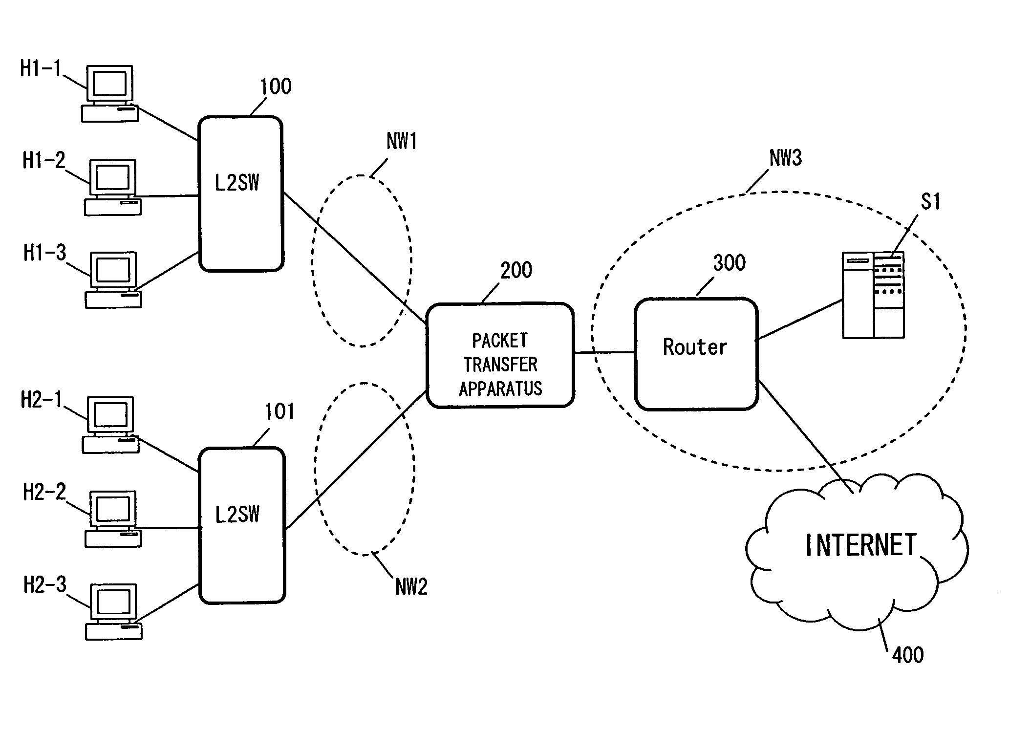
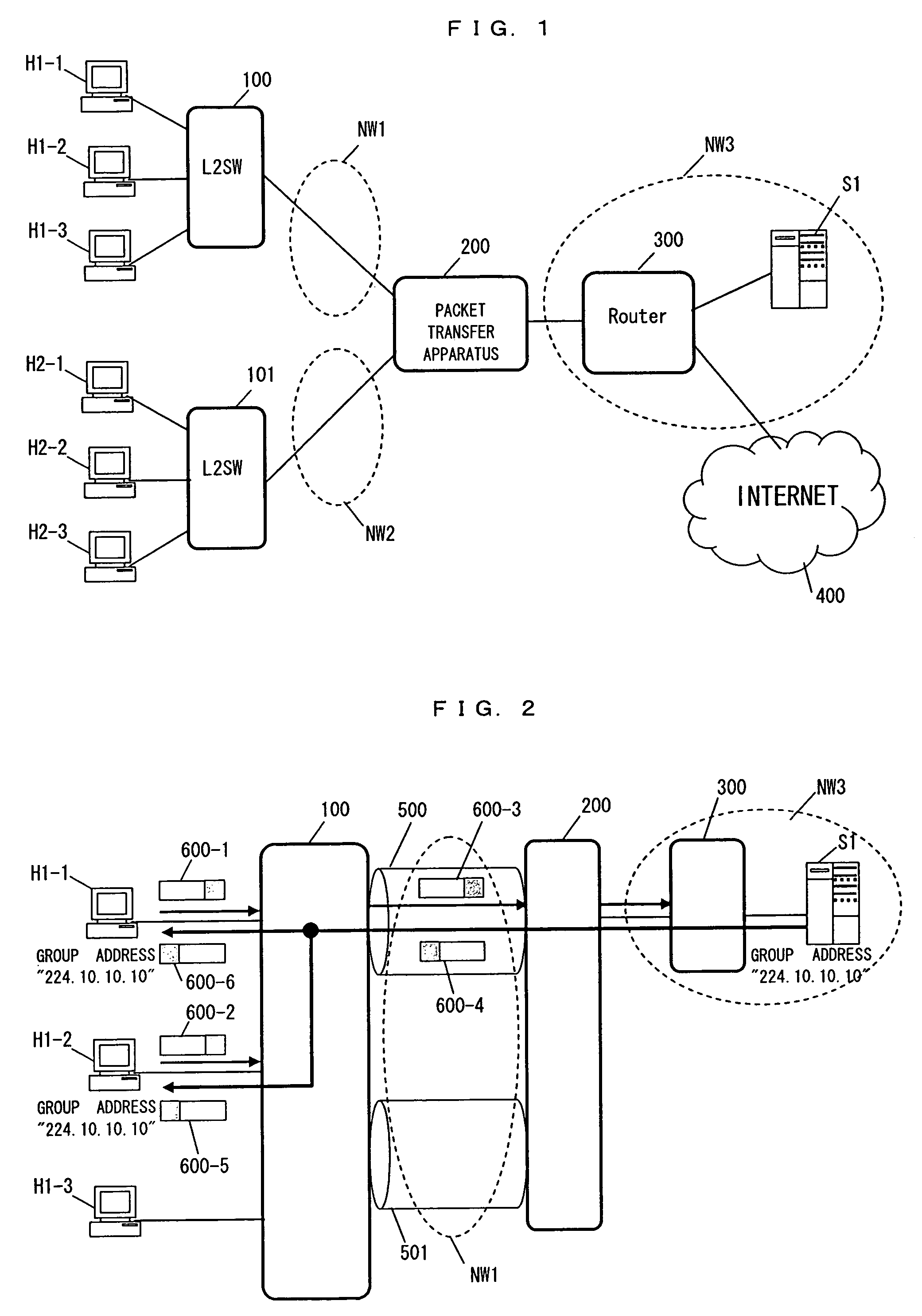
[0009]Accordingly, it is an object of the present invention to minimize a bandwidth wasted between the Layer 2 switch and the packet transfer apparatus by managing the user terminals and implementing multicast copy distribution by means of the Layer 2 switch.
[0010]Another object of the present invention is to implement a multicast packet distribution function including multicast packet distribution destination management by the Layer 2 switch, by taking out an IGMP packet or an MLD packet sent from the user terminal selectively from a PPP connection. A further object of the present invention is to reduce the internal load of the access carrier network and suppress the equipment cost, by making a dynamic or static multicast connection between the Layer 2 switch and the packet transfer apparatus and letting the Layer 2 switch receive a multicast packet as a representative of the plurality of multicast user terminals connected to it.
[0012]The conventional Layer 2 switch cannot perform multicast packet distribution together with multicast packet distribution destination management. A Layer 2 switch of the present invention can implement multicast packet distribution involving multicast packet distribution destination management by taking out an IGMP packet or an MLD packet coming from the user selectively from a PPP connection. A dynamic or static multicast connection is made between the Layer 2 switch and a packet transfer apparatus, and the Layer 2 switch receives a multicast packet as a representative of the plurality of multicast user terminals connected to it, so that the internal load of the access carrier network can be minimized and the facility cost can be reduced.

Problems solved by technology

The conventional Layer 2 switch cannot perform multicast packet distribution together with multicast packet distribution destination management.

Method used


Image

  • Layer 2 switch
  • Layer 2 switch
  • Layer 2 switch

Examples


case 1

(Case 1 of Leaving a Multicast Group)

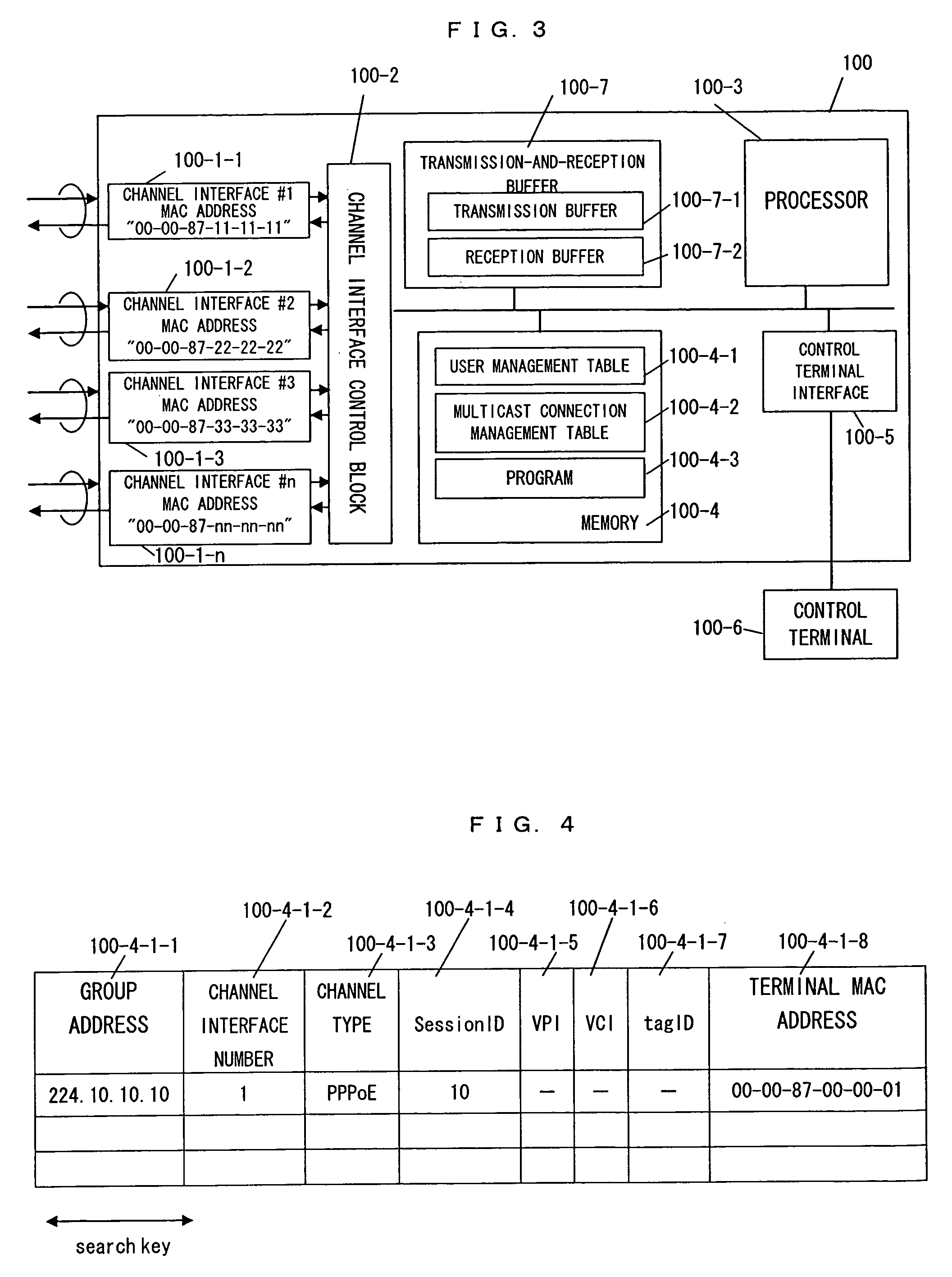
[0078]The operation of the Layer 2 switch performed when a user terminal leaves a multicast group will next be described. The sequence of leaving a multicast group depends on whether the user terminal makes a request of leaving explicitly or not. The user terminal is assumed not to make a request of leaving explicitly when the user terminal becomes out of order, for instance.

[0079]FIG. 12 shows a sequence in which the user terminal H1-1 and the user terminal H1-2 make a request of leaving explicitly.

[0080]The user terminal H1-2 wants to leave the multicast group with group address “224.10.10.10” and indicates the intention to leave by sending an IGMP leave packet (SQ2-1). The IGMP leave packet reaches channel interface #2 of the Layer 2 switch 100 and is transferred to the channel interface control block 100-2, which transfers the packet to the reception buffer 100-7-2 and generates an interrupt to notify the processor 100-3 that the packet has b...

case 2

(Case 2 of Leaving a Multicast Group)

[0087]FIG. 13 shows a sequence of stopping distribution from the content distribution server S1 when the user terminal H1-1 and the user terminal H1-2 leave the multicast group with group address “224.10.10.10”, without indicating their intention to leave explicitly, such as when a user terminal failure occurs.

[0088]The Layer 2 switch 100 sends an IGMP query packet to the user terminals included in the user management table 100-4-1 successively in order to check whether they are connected (SQ3-1). If the user terminal H1-2 operates normally, the user terminal H1-2 returns an IGMP response packet (SQ3-2). If no response is returned, the Layer 2 switch 100 considers that the user terminal H1-2 is not connected and deletes the user information of the user terminal H1-2 from the user management table 100-4-1 (SQ3-3). After the user terminal information is deleted from the user management table 100-4-1, the user management table 100-4-1 is searched th...


PUM


Abstract

A Layer 2 switch manages distribution destinations of a multicast packet and distributes a copy of the multicast packet, so that the bandwidth wasted in a network is reduced. The Layer 2 switch is disposed between a user terminal and a packet transfer apparatus, which are connected by P2P, has a function to manage connected multicast users, receives a multicast packet on behalf of the users, and distributes a copy, to reduce the bandwidth wasted between the Layer 2 switch and the packet transfer apparatus.

Description

BACKGROUND OF THE INVENTION[0001]1. Field of the Invention[0002]The present invention relates to Layer 2 switches, and more specifically, to a Layer 2 switch for copying a multicast packet, in multicast packet transfer used for content information distribution such as broadcasting.[0003]2. Description of the Related Art[0004]In the initial stage of the spread of the Internet among the general public, Internet access was obtained in most cases by a direct dial-up connection to an access point of an Internet service provider (ISP) and authentication. A commonly used protocol is Point-to-Point Protocol (PPP), which supports an authentication function and a compression function. PPP is a Layer-2-class protocol for making a one-to-one connection between a user terminal and an ISP access point. In this age of broadband, a connection by an access carrier network using Internet Protocol (IP) has become the mainstream of connection between a user terminal and an ISP, instead of a connection ...

Claims


Application Information

Patent Timeline
Patent Type & Authority Patents(United States)
IPC IPC(8): H04L12/28H04L12/44
CPCH04L12/18
Inventor IKEDA, KOJIMIYATA, HIROAKIOTA, MIGAKU
Owner HITACHI LTD
Why Eureka
Try Eureka