Packet transmission apparatus

Inactive Publication Date: 2007-09-20
FUJITSU LTD
View PDF14 Cites 36 Cited by
  • Summary
  • Abstract
  • Description
  • Claims
  • Application Information

AI Technical Summary

Benefits of technology

[0011] When the transmission of a segment has failed, as the transmission of any other segment remaining to be transmitted in the packet of which the failed segment forms a part is stopp

Problems solved by technology

When the retransmission control is implemented at the higher layer as shown in FIG. 1, if a certain segment fails

Method used


Image

  • Packet transmission apparatus
  • Packet transmission apparatus
  • Packet transmission apparatus

Examples


second embodiment

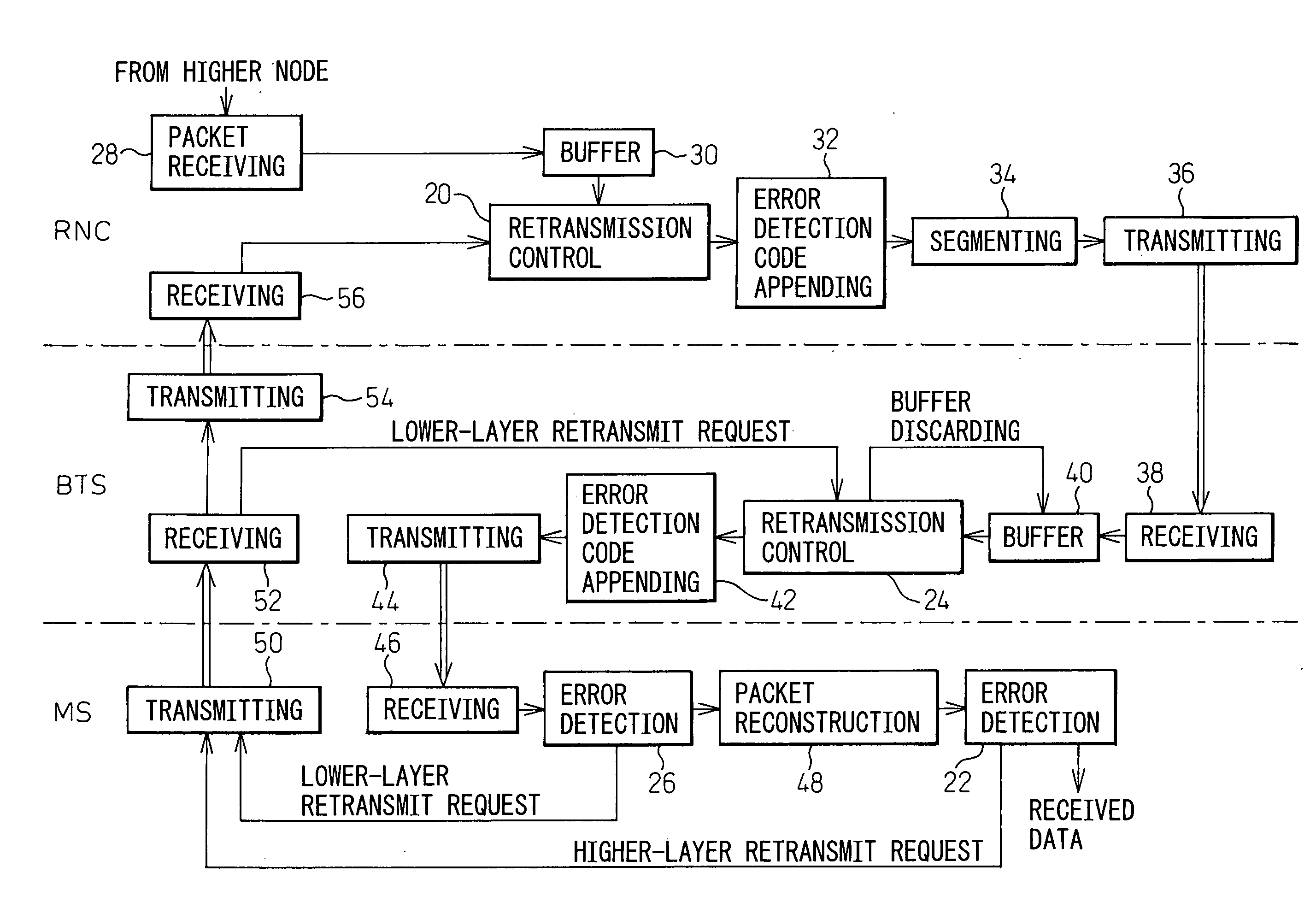
[0028]FIG. 4 shows the configuration of a mobile communication system according to the present invention. The difference from the embodiment of FIG. 3 is that, when the preset number of retransmissions or the preset timer count is reached in the retransmission control unit 24 at the lower layer, not only is the data stored in the buffer 40 discarded but, at the same time, a higher-layer retransmit request is issued from the retransmission control unit 24 and transmitted to the higher layer via the transmitting unit 54 and the receiving unit 56. Here, as described above, in response to the data delivery failure and the data discarding at the lower layer, the retransmission from the higher layer is initiated after a prescribed time has elapsed but, in this embodiment, the retransmission can be initiated without delay by issuing the retransmit request from the retransmission control unit 24 at the lower layer to the retransmission control unit 20 at the higher layer upon discarding the...

third embodiment

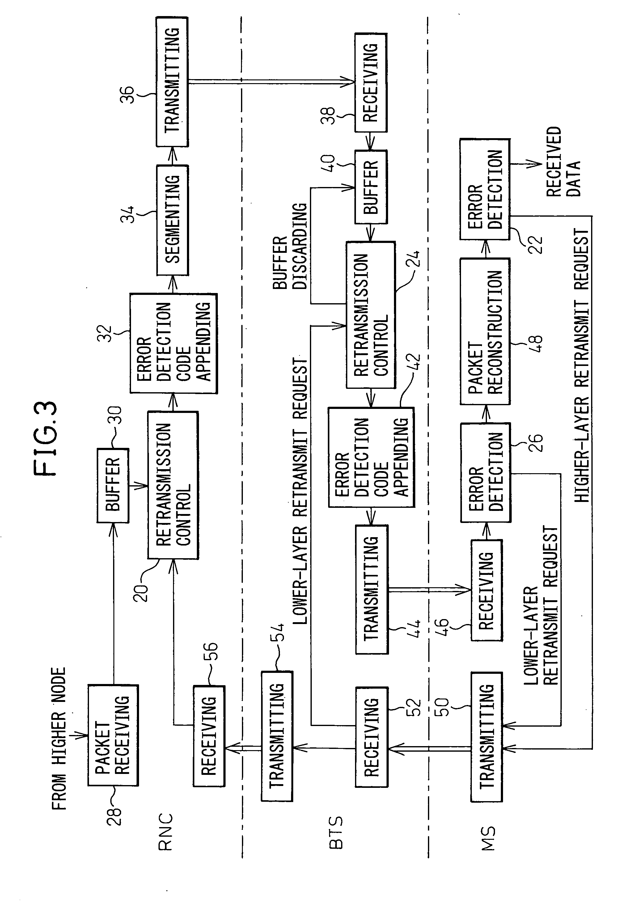
[0029]FIG. 5 shows the configuration of a mobile communication system according to the present invention. The difference from the embodiment of FIG. 3 is that when a notification of the occurrence of an uncorrectable error is received from the error detection processing unit 26 at the lower layer, the unit 24 does not retransmit the segment, but immediately discards the contents of the buffer 40. In this way, in the present invention, the retransmission control at the lower layer is not an essential requirement.

[0030] In the embodiment of FIG. 5, the retransmit request may be issued to the higher layer upon discarding the contents of the buffer 40, as in the embodiment of FIG. 4.

[0031] When applying the packet transmission method of the present invention, necessary information associated with segmentation must be appended to each segment. One example is shown in FIG. 6. As shown in FIG. 6, when dividing the higher-layer packet into segments, information identifying the segment posi...


PUM


Abstract

Wasteful use of radio resources is minimized in a packet transmission system which performs retransmission control at a higher layer. When transmission of a segment has failed at a lower layer and, for example, when the number of lower-layer retransmit requests from an error detection unit at the lower layer has exceeded a predetermined threshold, any other segment remaining to be transmitted in a packet of which the failed segment forms a part is discarded and, at the same time, a retransmit request is sent to a retransmission control unit at the higher layer.

Description

BACKGROUND OF THE INVENTION [0001] 1. Field of the Invention [0002] The present invention relates to a packet transmission apparatus and, more particularly, to a packet transmission apparatus suitable for application to a base transceiver station and a mobile station in a mobile communication system. [0003] 2. Description of the Related Art [0004] In communications using radio waves and, in particular, communications between base transceiver stations (BTSs) and mobile stations (MSs) in a mobile communication system, it is important that radio resources, such as frequencies and spreading codes, be utilized effectively. The reason is that, in a mobile communication system, limited radio resources linking between each BTS and MSs are shared by many users and, if the radio resources can be utilized effectively, more users can be accommodated in the system. [0005] On the other hand, in a W-CDMA (Wideband Code Division Multiple Access) system, for example, in addition to the retransmissio...

Claims


Application Information

Patent Timeline
IPC IPC(8): H04J1/16H04L1/16H04W28/00H04L47/43H04W28/04H04W28/06
CPCH04L1/1809H04L1/1877H04W28/06H04L2001/0092H04W28/04H04L1/188H04L1/0041H04W28/065
Inventor KAWABATA, KAZUOOBUCHI, KAZUHISATAJIMA, YOSHIHARU
Owner FUJITSU LTD
Why Eureka
Try Eureka