
VOCs pre-collecting treatment system with water seal and treatment method of VOCs pre-collecting treatment system

A treatment system and pre-collector technology, applied in the direction of combustion methods, lighting and heating equipment, combustion types, etc., can solve problems such as complex components, false alarms, inability to provide early warning and reduce VOCs, etc., to enhance the ability to change working conditions , prevent explosion accidents, and the overall structure is simple

Pending Publication Date: 2019-08-27
CHINA NAT AIR SEPARATION ENG CO LTD
View PDF0 Cites 1 Cited by
  • Summary
  • Abstract
  • Description
  • Claims
  • Application Information

AI Technical Summary

Problems solved by technology

There are two problems in the current technology: 1. The composition of VOCs is complex, generally there are at least two to three components, and some VOCs even have dozens of combustible gas components, and the current combustible gas concentration monitor can only monitor one at most four This causes the combustible gas concentration monitor to be unable to really warn the real concentration of combustible gas mixture, causing false alarms or non-reporting
2. It takes a certain time for the combustible gas concentration monitor to monitor and respond, and it also takes a certain time for the air valve to open. The sum of these two times generally takes 10~30S
This means that even if the combustible gas concentration monitor can give an accurate warning, when the air valve is opened, it will take at least 10~30 seconds to reduce the VOCs concentration. Calculated at a gas flow rate of 3m / s, the combustible gas monitor and the damper must be set at least 30-90 meters away from the entrance of the RTO, but many factories cannot actually reach this distance, so it is impossible to achieve the purpose of early warning and reduction of VOCs concentration

Method used


Image

  • VOCs pre-collecting treatment system with water seal and treatment method of VOCs pre-collecting treatment system

Examples


Embodiment

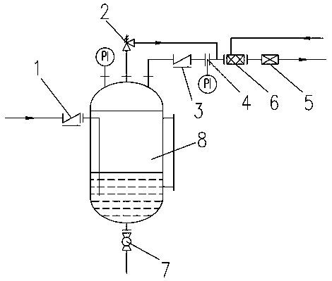
[0031] Example: VOCs waste gas released by the vent valve of the reactor or the breather valve of the storage tank (the main components are: toluene, xylene, ethyl acetate, Q=0.18m 3 / h, P=0.3MPa), through the exhaust gas main pipe (DN100), through a back pressure valve (BY-S100 / 0.5) into the pre-collection device 8 (working pressure 0.5MPa, volume 2m 3 ), with safety valve 2 (A62H5H), which is discharged after passing through the water seal, through the check valve 3 (H61H-3R), through the flow limiting orifice 4 (single-hole veneer, d=0.06m) to regulate the stable exhaust gas flow, and enter In the gas mixer 6, inert gas (Q=1.2m) is passed into the gas mixer 6 (SH L / D=6) 3 / h) mixed with exhaust gas to ensure that the concentration of exhaust gas is lower than 25% of the lower explosion limit, and the mixture of inert gas and exhaust gas passes through the flame arrester 5 continuously and stably before entering the RTO device.

[0032] The purpose of the present invention ...


PUM


Abstract

The invention discloses a VOCs pre-collecting treatment system with a water seal and a treatment method of the VOCs pre-collecting treatment system. A pre-collector, a waste gas main pipeline arrangedat one side position of the pre-collector, a first pipeline arranged at the bottom of the pre-collector, a second pipeline arranged on the top of the pre-collector, a third pipeline arranged on the top of the pre-collector and an RTO device arranged at the tail end of the third pipeline are included. The waste gas main pipeline is connected with the pre-collector and stretches to the position below the liquid level of the pre-collector. The second pipeline is provided with a safety valve, one end of the second pipeline is connected with the pre-collector, and the other end of the second pipeline is connected to the third pipeline. The third pipeline is provided with a check valve and a gas mixer, a flow limiting hole plate is arranged between the check valve and the gas mixer, the gas mixer is externally connected with a connecting pipeline, and inflation of inert gas is conducted through the connecting pipeline. The VOCs pre-collecting treatment system has the beneficial effects thatthe integral structure of the device is simple, safety and stability are achieved, RTO production explosion accidents are effectively prevented, and the variable work condition capability of the RTOdevice is enhanced.

Description

technical field [0001] The invention relates to the technical field of chemical pretreatment systems, in particular to a VOCs pre-collection and treatment system with a water seal and a treatment method thereof. Background technique [0002] In the fields of petroleum, chemical industry, medicine and coating, organic waste gases of hydrocarbons such as alkanes, olefins, alcohols, ketones, ethers, esters, aromatics and benzene are basically involved. At present, with the continuous improvement of environmental protection requirements for VOCs remediation, regenerative waste gas incinerator (RTO) has been more widely used in the treatment of organic waste gas in intermittent production enterprises such as chemical industry and medicine. However, the composition of waste gas in these industries is complex and changeable. The concentration fluctuates greatly. The existing waste gas collection system and pretreatment system are difficult to control the concentration of mixed comb...

Claims


Application Information

Patent Timeline
Patent Type & Authority Applications(China)
IPC IPC(8): F23G7/06F23G5/02
CPCF23G7/06F23G5/02F23G2201/70F23G2209/14Y02A50/20
Inventor 徐向晖陆棋王红伟楼松楼生龙毛利敢
Owner CHINA NAT AIR SEPARATION ENG CO LTD
Learn More