
Wind turbine

a wind turbine and turbine blade technology, applied in the field of wind turbines, can solve the problems of fatigue in the blades and other rotor components, the need for structurally robust and costly towers to support the weight of elevated equipment, and the flexing of the blades of the rotor

Inactive Publication Date: 2006-05-09
KANE VIC
View PDF10 Cites 107 Cited by
  • Summary
  • Abstract
  • Description
  • Claims
  • Application Information

AI Technical Summary

Benefits of technology

The hybrid design achieves higher efficiency and reduced complexity by leveraging higher wind speeds above the ground while minimizing tower stress and maintenance needs, offering a balance between vertical and horizontal axis turbine performance.

Problems solved by technology

A structurally robust and costly tower is required to support the weight of the elevated equipment.
Likewise, the pressure pulse created by the wind shading of the tower causes the blades of the rotor to flex inducing fatigue in the blades and other rotor components.
Maintenance of horizontal axis turbines can be complex because the equipment is located at the top of the tower.
While horizontal axis wind turbine installations are relatively complex and expensive, they are the most common wind turbine configurations in current use.
The efficiency of a Savonius turbine is limited because power produced by the gathering side of the rotor is offset by drag produced by the other side of the rotor.
In addition, since the area of the scoops exposed to the wind flow varies as the turbine rotates, the torque is not even throughout a revolution of the shaft and no torque will be produced to initiate rotation if the rotor is improperly aligned with the wind flow.
While this type of turbine can produce high torque and can be useful for pumping water and similar tasks, the speed of rotation is generally too slow for efficient production of electricity, a major use of commercial wind turbines.
While vertical axis wind turbine installations are potentially less complex and costly than horizontal axis turbines, the lack of commercial success of vertical axis turbines is indicative of substantial drawbacks of this type of turbine.
However, wind speeds close to the ground are very low and turbulent due to boundary layer effects.
As a result, the output of a vertical axis turbine, particularly the lower half of the rotor, is limited and the overall efficiency is relatively low.
Further, guy wires may be required to stabilize the vertical shaft which may make the turbine impractical in extensively farmed or built-up areas.

Method used


Image

  • Wind turbine
  • Wind turbine
  • Wind turbine

Examples


Embodiment Construction

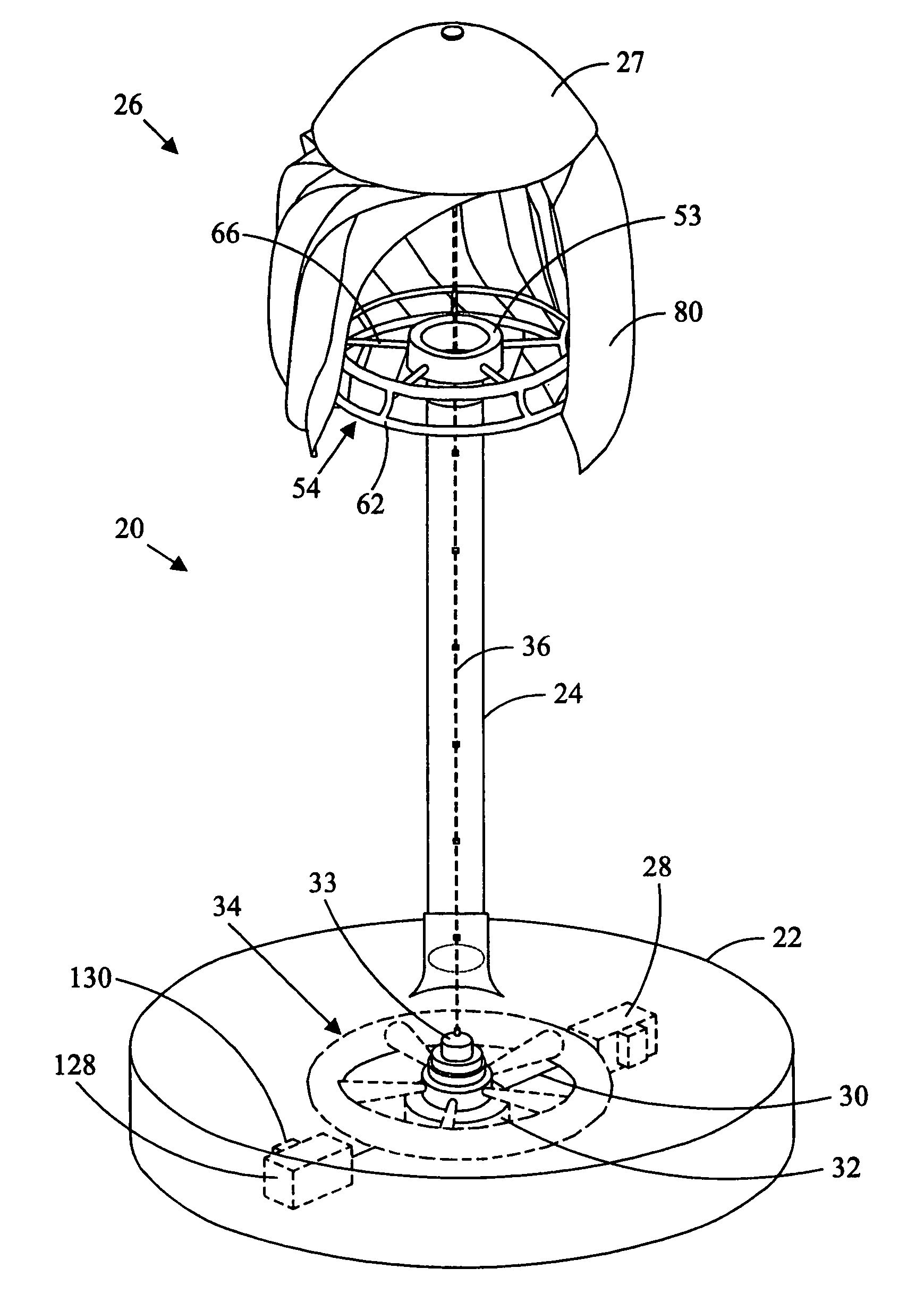
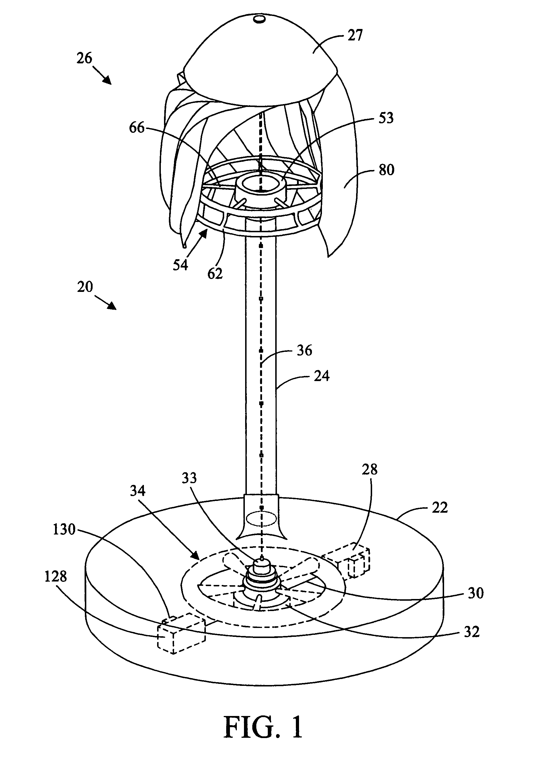
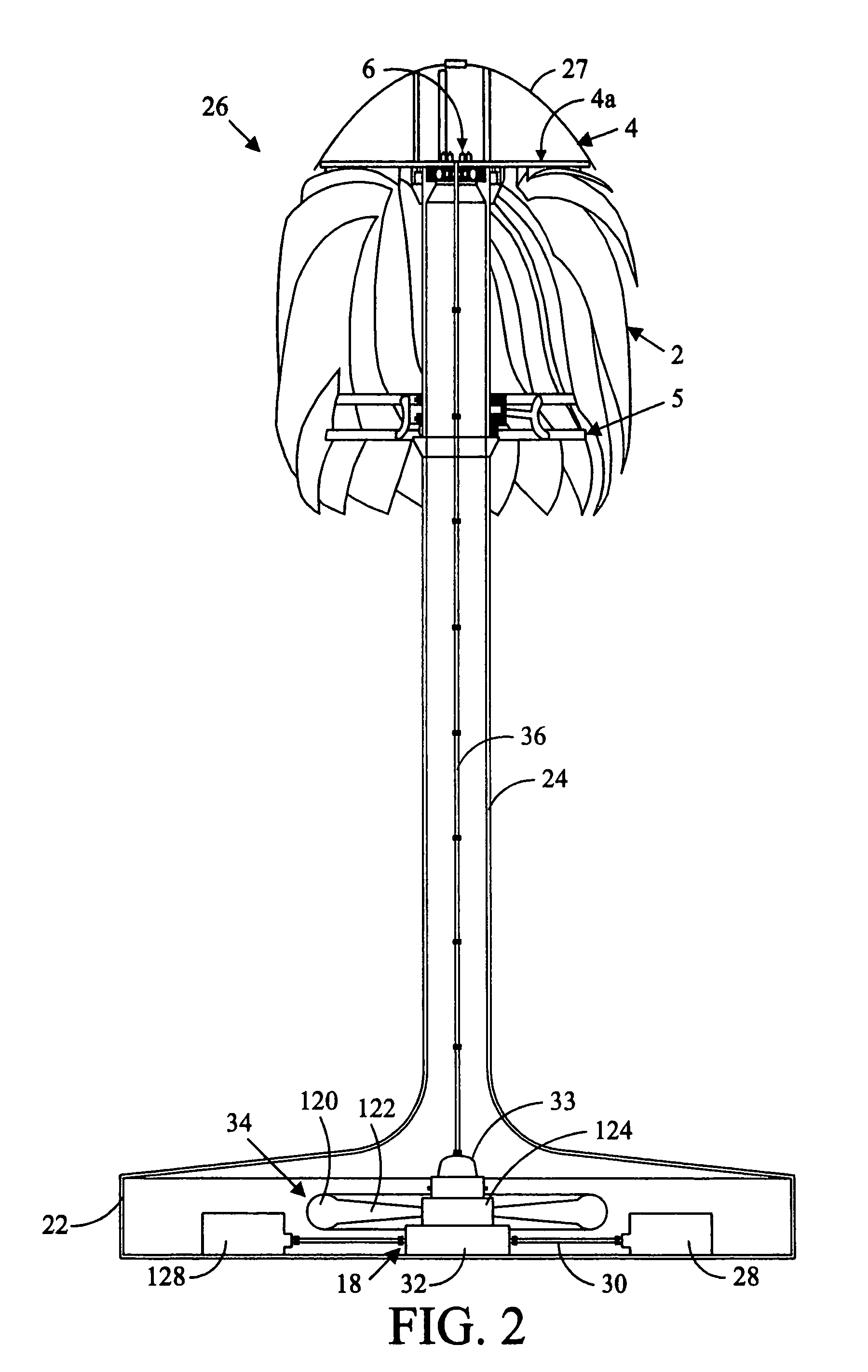
[0018]Referring in detail to the drawings wherein similar parts of the invention are identified by like reference numerals, and, more specifically to FIGS. 1 and 2, a wind power energy converter for generating electricity 20 is illustrative of a vertical axis embodiment of the inventive wind turbine system. The energy converter installation 20 comprises, generally, a foundation or base 22 supporting a tower 24 which, in turn, supports the wind turbine 26. One or more electric power generators 28 are located on the foundation 22 and driven by a flywheel 34. The generators 28 are connected to the flywheel 34 by drive shafts 30 that are connected to a right-angle drive 32 that is rotatably connected to the flywheel. The right angle drive 32 may also include variable ratio gearing or other power transmission components, such as a hydrostatic pump and motor, to control the speed of rotation of the generator 28 under variable wind conditions. A power transmission apparatus rotatably conne...


PUM


Abstract

A wind turbine operable as either a vertical axis wind turbine or a horizontal axis wind turbine is disclosed.

Description

CROSS-REFERENCE TO RELATED APPLICATIONS[0001]Not applicable.BACKGROUND OF THE INVENTION[0002]The present invention relates to a wind turbine.[0003]Modern wind turbines are divided into two major categories: horizontal axis turbines and vertical axis turbines. Horizontal axis wind turbines typically comprise a tower and a fan-like rotor mounted at the top of the tower for rotation about an axis substantially parallel to the earth's surface. The rotor of a horizontal axis wind turbine must face either into or away from the direction of the wind and a yaw mechanism is required to rotate the rotor about the vertical axis of the tower to keep the rotor in proper alignment with the wind flow. Since a mechanical means of delivering power to the ground could cause the rotor to yaw out of alignment with the wind, energy conversion devices, such as generators; power transmission equipment; and related equipment are typically also mounted atop the tower. A structurally robust and costly tower ...

Claims


Application Information

Patent Timeline
Patent Type & Authority Patents(United States)
IPC IPC(8): F03D7/06F03D3/06F03D7/00F03D9/02
CPCF03D3/061F03D9/02Y02E10/74F03D13/22F03D9/10Y02E60/16Y02E10/728F03D9/12Y02E70/30
Inventor KANE, VIC
Owner KANE VIC
Learn More