Rotatable axial fan

a technology of axial fan and rotating shaft, which is applied in the direction of rotating shafts, marine propulsion, vessel construction, etc., can solve the problems of inability to sleep, and inability to achieve maximum cooling effect, so as to increase oscillation speed, increase oscillation speed, and reduce fan speed

Inactive Publication Date: 2009-08-27
CRAIG TREVOR
View PDF9 Cites 123 Cited by
  • Summary
  • Abstract
  • Description
  • Claims
  • Application Information

AI Technical Summary

Benefits of technology

[0014]The apparatus may be operated by a control panel mounted on the axial fan and can also be operated by a remote control. The remote control may be wired or wireless. If wireless, the remote control may transmit control commands via radio or optical signals. The following are operational commands that may be activated and/or programmed by the control panel: power on, power off, initiate standby mode, in...

Problems solved by technology

Hot nights make sleeping difficult.
These fans can also be placed on the floor, but the maximum cooling effect is not achieved unless the bed is very low to the floor.
Box fans can also be placed on a desk or table near the bed, but not every bedroom has a desk or table near the bed such that the maximum cooling effect cannot be achieved.
Additionally it may be awkward, cumbersome, or even dangerous to place a relatively large box fan on a small table or desk.
Circular fans are also available to provide air movement; however, they have the same difficulties as a box fan in that they must be located near a bed to achieve the maximum cooling effect while a person is sleeping.
And locating a circular fan near a bed may not always be possible.
A drawback to a circular fan is that it has a direction of airflow similar to a cone.
Placing the fan near a bed can maximize the cooling effect, but this results in only a portion of the bed receiving the benefit of the increased airflow while another portion of the bed is without t...

Method used


Image

  • Rotatable axial fan
  • Rotatable axial fan
  • Rotatable axial fan

Examples


Embodiment Construction

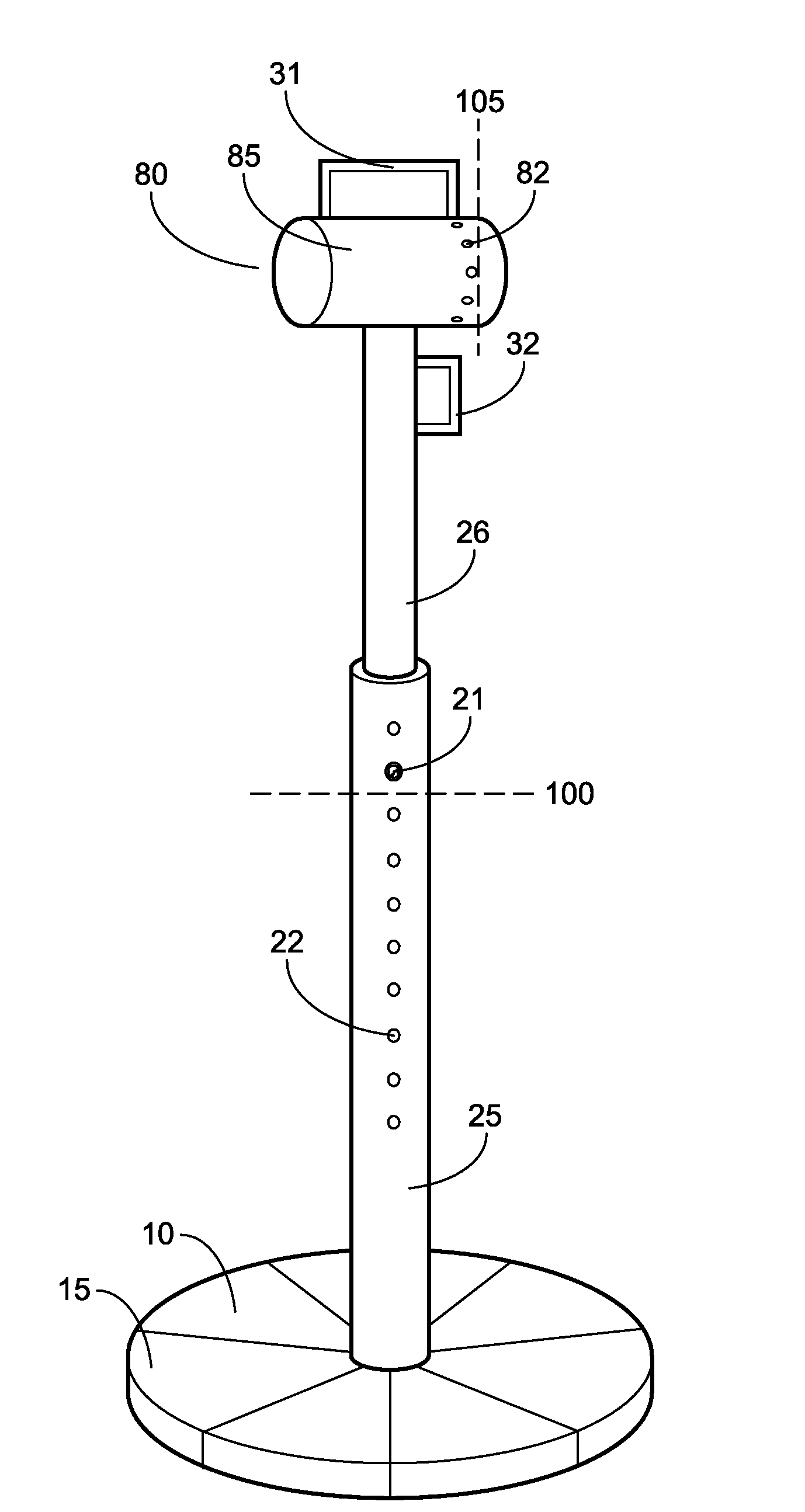
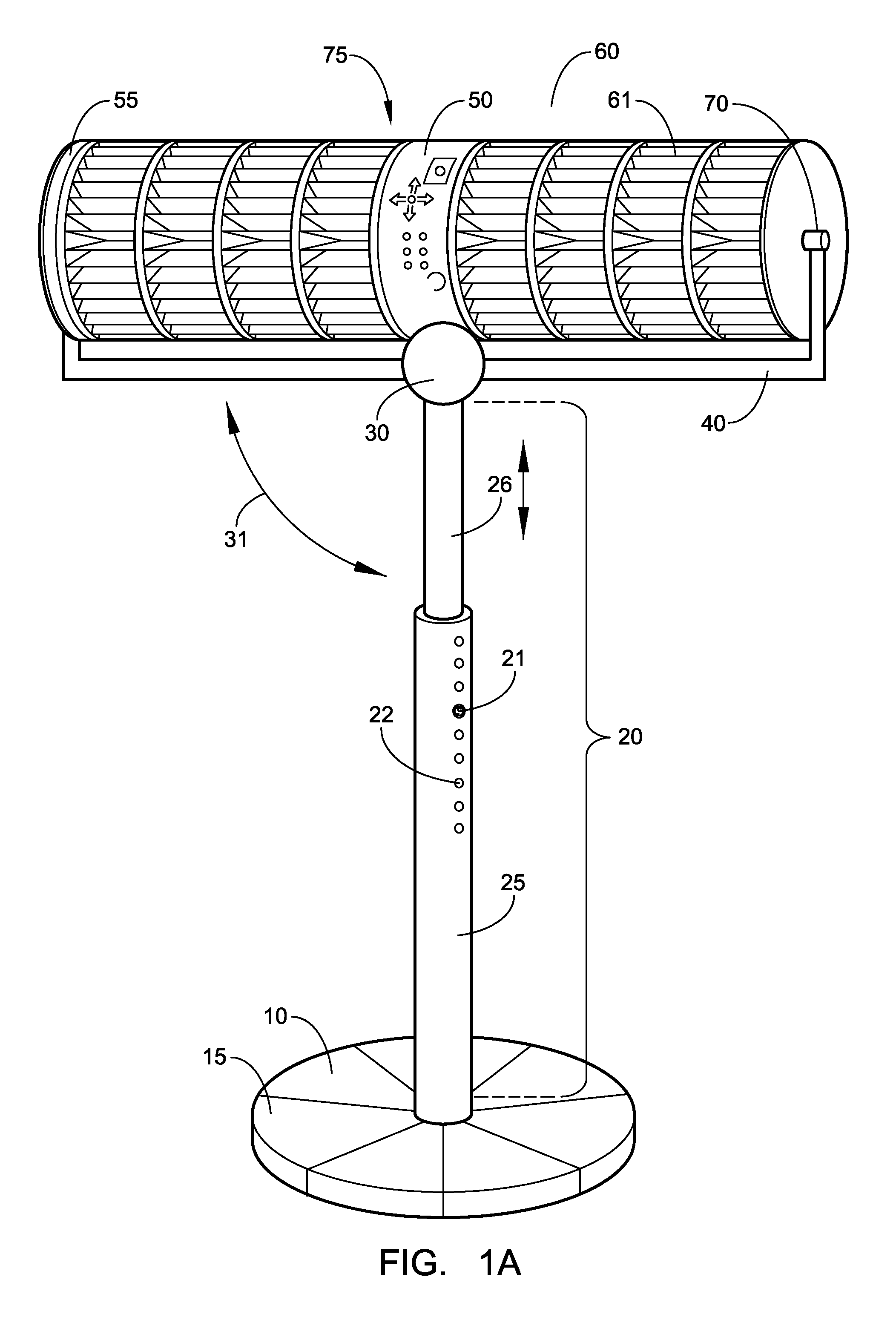
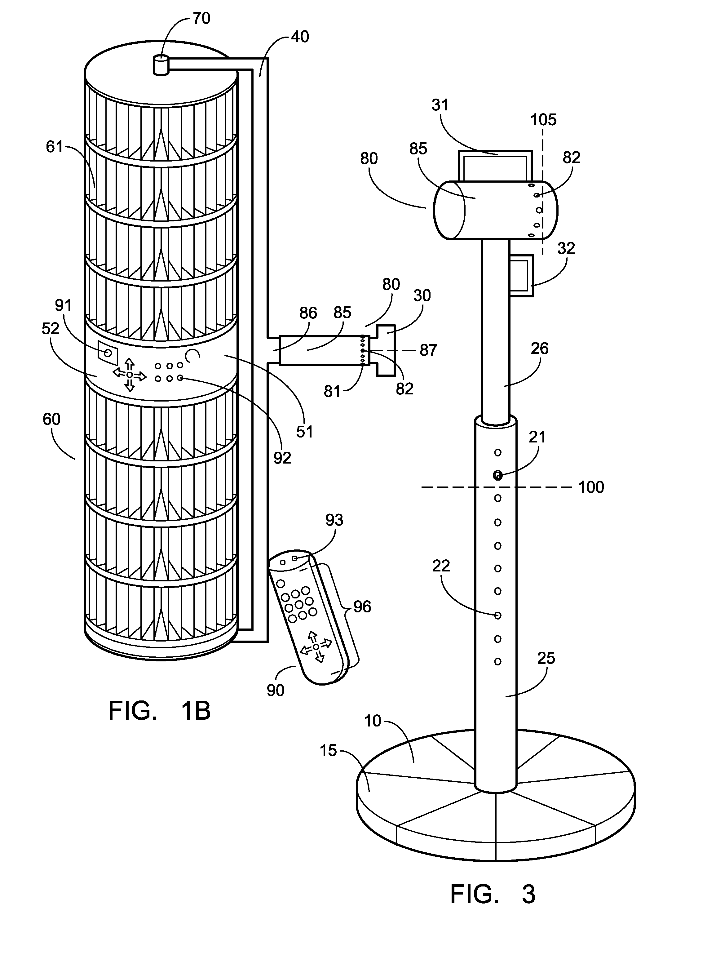
[0021]A novel apparatus for the movement of air is provided to direct the movement of air to maximize comfort. As illustrated in FIG. 1A, the apparatus (1) is adjustable so that the vertical distance of the axial fan (60) from the base (10) is variable by means of a telescoping mechanism. Vertical support member (20) is comprised of a first section (25) and a second section (26). First section (25) and second section (26) are slidably coupled. The second section (26) is dimensioned concentrically smaller than first section (25) so that second section (26) is received by first section (25). This slidable coupling allows the vertical support member (20) to telescope, extending the member (20) when the second section (26) is pulled out the first section (25) and collapsing the member (20) when the second section (26) is pushed into the first section (25). The vertical support member (20) may also comprise a plurality of sections more than the two illustrated in FIG. 1A.

[0022]The length...


PUM


Abstract

The present disclosure provides a novel apparatus for the movement of air. Specifically, the apparatus is an axial fan assembly which is rotatable about a horizontal axis to orient the axial fan in a vertical position, a horizontal position, or positions in between. The axial fan can be adjusted and selectively fixed in a particular orientation. The height of the axial fan is also adjustable. The vertical support member comprises a telescoping mechanism whereby the length of the vertical support member is adjustable and can be selectively fixed at a particular length.

Description

PRIORITY[0001]This patent application claims priority to provisional patent application no. 61 / 031,104, entitled “Rotatable Tower Fan”, filed by Trevor Craig on Feb. 25, 2008.FIELD OF THE INVENTION[0002]The present invention relates to an apparatus for the movement of air.BACKGROUND OF THE INVENTION[0003]Hot nights make sleeping difficult. The movement of air around a person can make them more comfortable. Various types of motorized fans are known for their cooling properties and have been used in bedrooms to make sleeping more comfortable. Motorized fans can also add comfort in otherwise hot and stuffy environments. Several types of fans exist, including box fans, circular fans, tower fans and ceiling fans.[0004]Box fans can be placed in windows. The fan's cooling effect is maximized only if a person's bed is situated near the window. These fans can also be placed on the floor, but the maximum cooling effect is not achieved unless the bed is very low to the floor. Box fans can also...

Claims


Application Information

Patent Timeline
IPC IPC(8): F04D17/02F04D29/22
CPCF04D29/601F04D25/08
Inventor CRAIG, TREVOR
Owner CRAIG TREVOR
Why Eureka
Try Eureka