
Cooling system with continuously variable capacity

a technology of continuously variable cooling capacity and compressor, which is applied in the direction of electrical equipment, electrical apparatus, electrical equipment contruction details, etc., can solve the problems of reducing the cooling capacity of the system, affecting the cooling efficiency of the system, so as to reduce the fan speed, reduce the cooling capacity, and increase the fan speed

Pending Publication Date: 2021-10-14
VERTIV CORP
View PDF0 Cites 0 Cited by
  • Summary
  • Abstract
  • Description
  • Claims
  • Application Information

AI Technical Summary

Benefits of technology

This patent describes a method for controlling the cooling capacity of a cooling system with a two-stage compressor and variable speed fan. The method involves running the compressor at a maximum speed when a maximum cooling capacity is needed, and then decreasing the fan speed as the cooling capacity decreases. This allows for efficient cooling at different levels of demand. The cooling system can also include multiple two-stage compressors and variable speed fans, which can be controlled to achieve even more precise cooling. Overall, this method and cooling system provide better cooling performance and efficiency.

Problems solved by technology

In addition, such systems can be subjected to part-load conditions wherein a system's maximum cooling capacity may not be needed or desired.
However, digital and variable speed compressors can have drawbacks such as noisy operation and / or relatively high costs of ownership.

Method used


Image

  • Cooling system with continuously variable capacity
  • Cooling system with continuously variable capacity
  • Cooling system with continuously variable capacity

Examples


Embodiment Construction

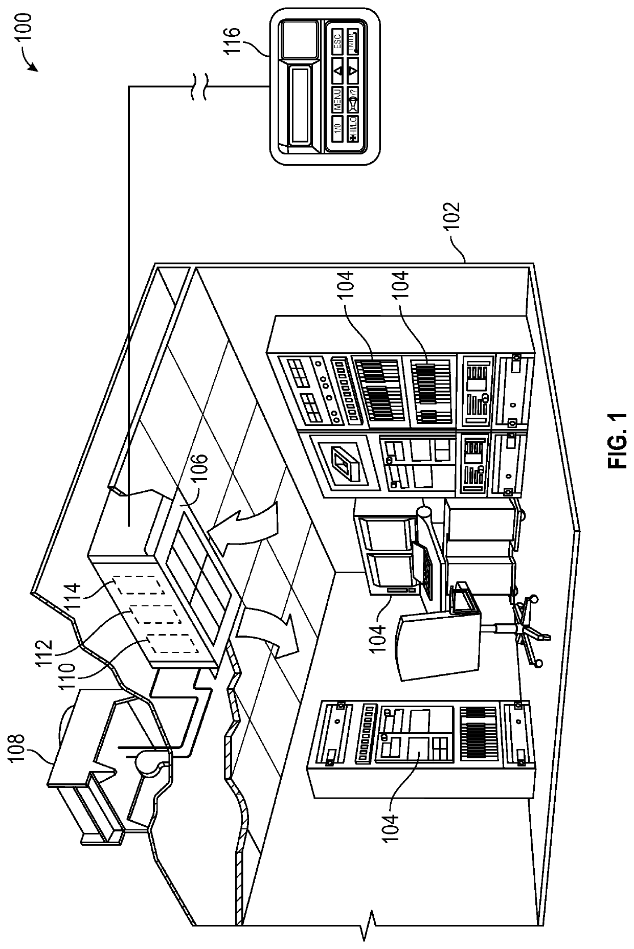
[0013]The Figures described above and the written description of specific structures and functions below are not presented to limit the scope of what Applicants have invented or the scope of the appended claims. Rather, the Figures and written description are provided to teach any person skilled in the art to make and use the invention(s) for which patent protection is sought. Those skilled in the art will appreciate that not all features of a commercial embodiment of the disclosure are described or shown for the sake of clarity and understanding. Persons of skill in this art will also appreciate that the development of an actual commercial embodiment incorporating aspects of the present disclosure can require numerous implementation-specific decisions to achieve the developer's ultimate goal for the commercial embodiment(s). Such implementation-specific decisions may include, and likely are not limited to, compliance with system-related, business-related, government-related and oth...


PUM


Abstract

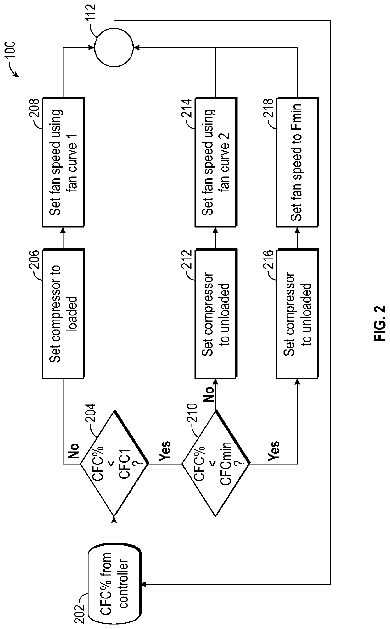
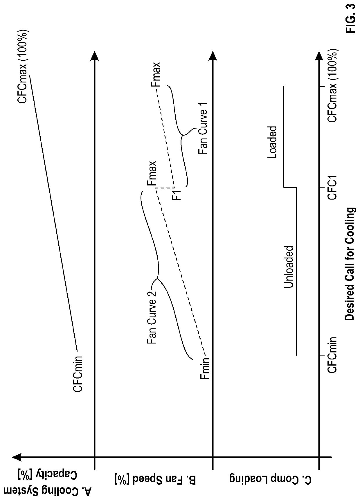
A cooling system can include a two-stage compressor, a variable speed fan and a controller for continuously modulating cooling capacity of the system. The compressor can run in a loaded state and the fan can run at a first speed when a call for cooling calls for maximum system cooling capacity. The compressor can run in the loaded state and the fan speed can decrease to a second fan speed as the called for cooling capacity decreases. The compressor can run in an unloaded state and the fan speed can be increased. The compressor can run in the unloaded state and the fan speed can decrease to a third fan speed as the called for cooling capacity decreases.

Description

CROSS REFERENCE TO RELATED APPLICATIONS[0001]This application claims the benefit of U.S. Provisional Patent Application No. 63 / 007,838 filed Apr. 9, 2020, the entire contents of which are hereby incorporated by reference herein.STATEMENT REGARDING FEDERALLY SPONSORED RESEARCH OR DEVELOPMENT[0002]Not applicable.REFERENCE TO APPENDIX[0003]Not applicable.BACKGROUND OF THE INVENTIONField of the Invention[0004]The present disclosure relates generally to cooling systems and more specifically relates to achieving continuously variable cooling capacity with a two-stage compressor and a variable speed fan.Description of the Related Art[0005]Cooling systems for server rooms utilized in edge computing and other relatively small information technology (IT) spaces often include components that operate within earshot of humans. For example, Liebert® Mini-Mate™ cooling units available from Vertiv Corporation (Columbus, Ohio) may be installed above false ceilings in server rooms or other spaces tha...

Claims


Application Information

Patent Timeline
Patent Type & Authority Applications(United States)
IPC IPC(8): H05K7/20
CPCH05K7/20836H05K7/20745H05K7/20827
Inventor JAIN, GAURAVBIRCHMEIER, JOHN R.MORENO, JACK A.
Owner VERTIV CORP
Learn More