
Method for controlling fan speed of electronic apparatus and electronic apparatus using the same

a technology of electronic equipment and fan speed, which is applied in the direction of non-positive displacement fluid engines, axial flow pumps, non-positive displacement pumps, etc., can solve the problems of inability to effectively dissipate heat outside the housing of electronic equipment, error in fan speed, and failure of electronic equipment to function properly, so as to improve the accuracy of fan speed control, increase the fan speed, and enhance the effect of heat dissipation efficiency

Active Publication Date: 2015-06-25
SPI ELECTRONICS
View PDF3 Cites 3 Cited by
  • Summary
  • Abstract
  • Description
  • Claims
  • Application Information

AI Technical Summary

Benefits of technology

This patent is about a method to control the speed of a fan in an electronic device. The method takes into account various factors like voltage and current to accurately calculate the fan speed needed to maintain a specific temperature. It then performs a close-loop control to ensure that the fan runs at the desired level, improving heat dissipation and preventing overheating. This results in better performance and reliability of the electronic device.

Problems solved by technology

However, even with the same speed control signal, an error in the fan speed may occur due to different fan specifications and / or wear (ageing) of the fan (the error may be up to hundreds or even thousands of revolutions).
If there is a large error in the fan speed, the fan may not be able to effectively dissipate heat outside the housing of the electronic apparatus.
As a result, the electronic apparatus may not function properly, which may very likely cause shutdown or unrecoverable damage to the hardware of the electronic apparatus.
With such a control mechanism, the internal temperature of the electronic apparatus may have become too high, or the circuits / devices inside the electronic apparatus may have been damaged due to high temperature when the temperature change is detected.
It would be too late to increase the fan speed to maintain the normal operation of the electronic apparatus.

Method used


Image

  • Method for controlling fan speed of electronic apparatus and electronic apparatus using the same
  • Method for controlling fan speed of electronic apparatus and electronic apparatus using the same
  • Method for controlling fan speed of electronic apparatus and electronic apparatus using the same

Examples


Embodiment Construction

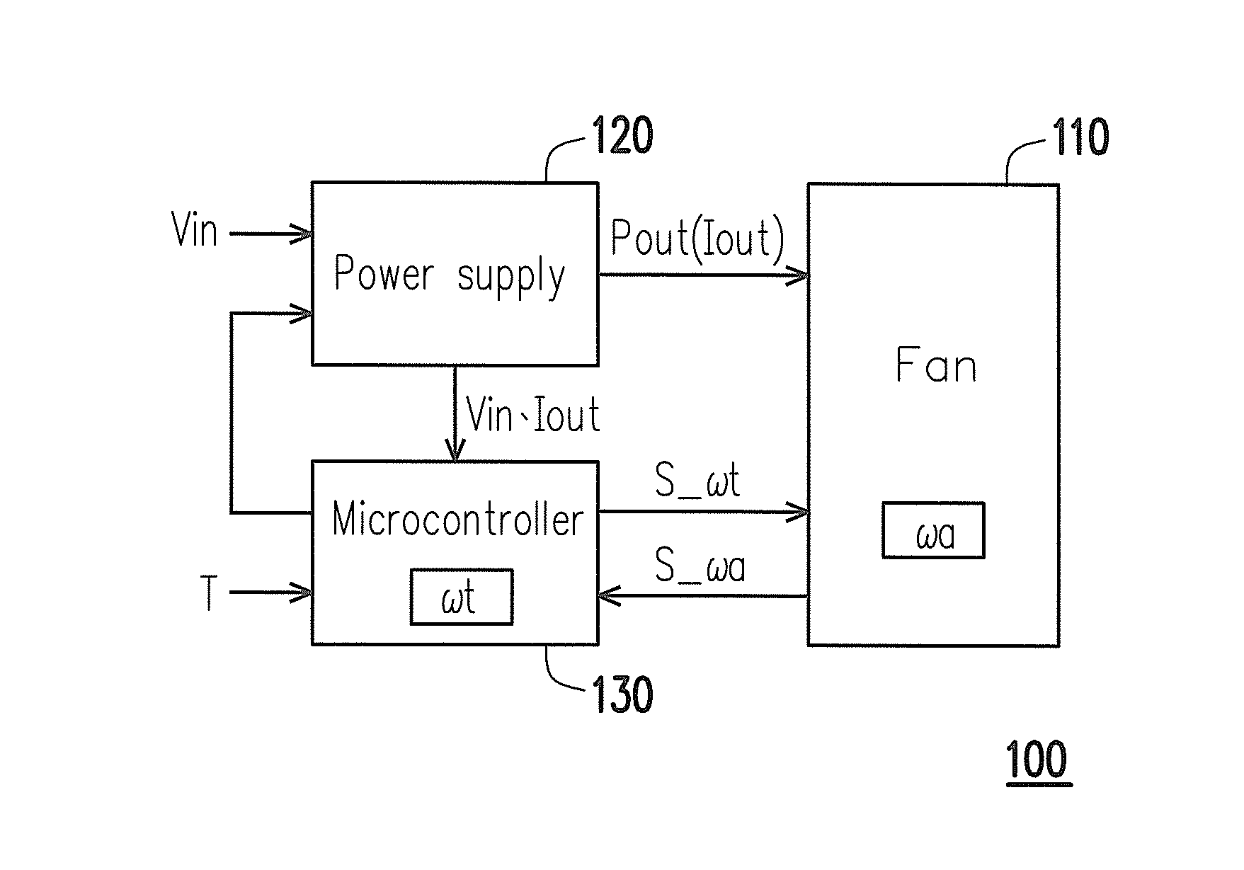
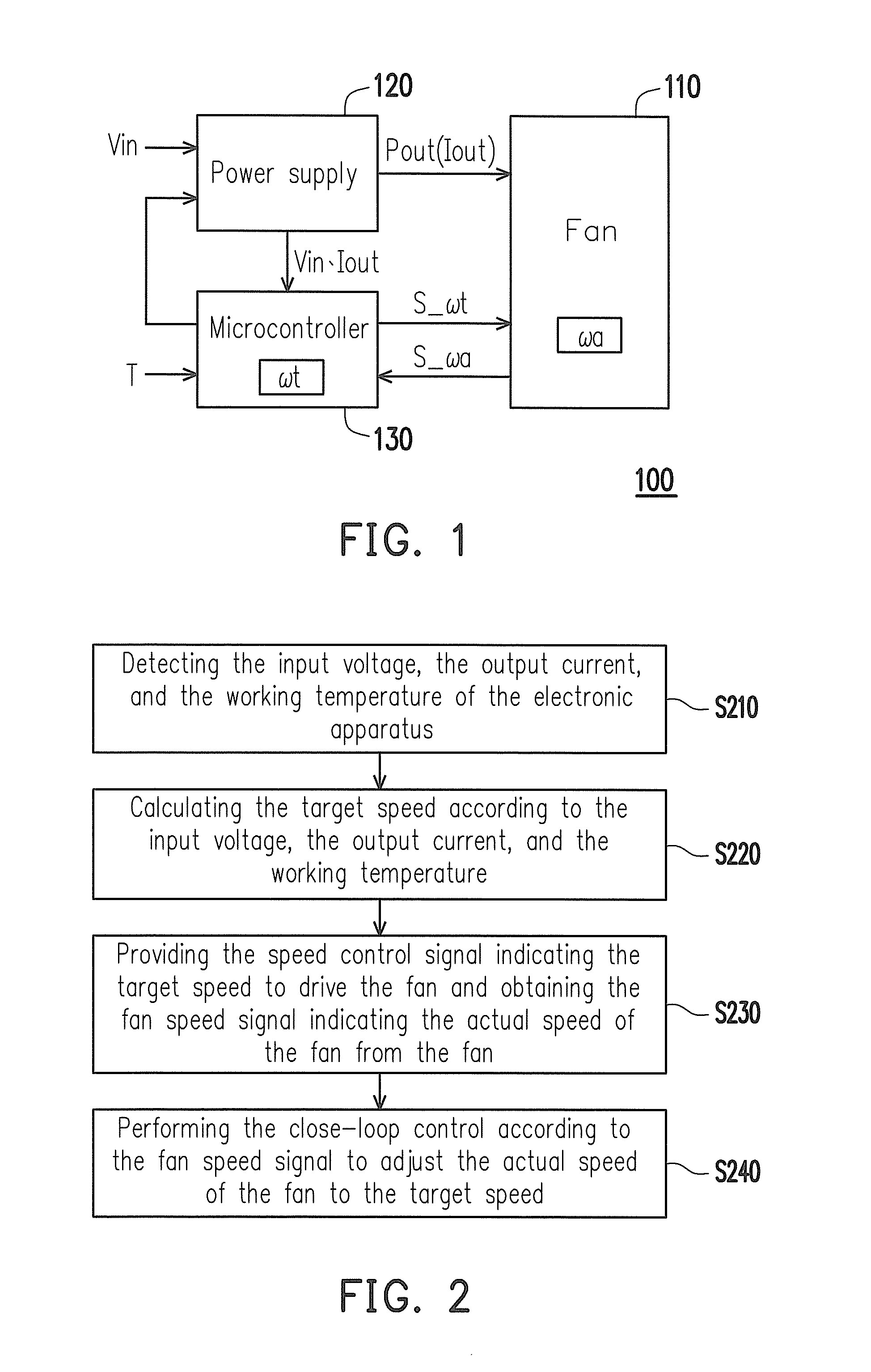
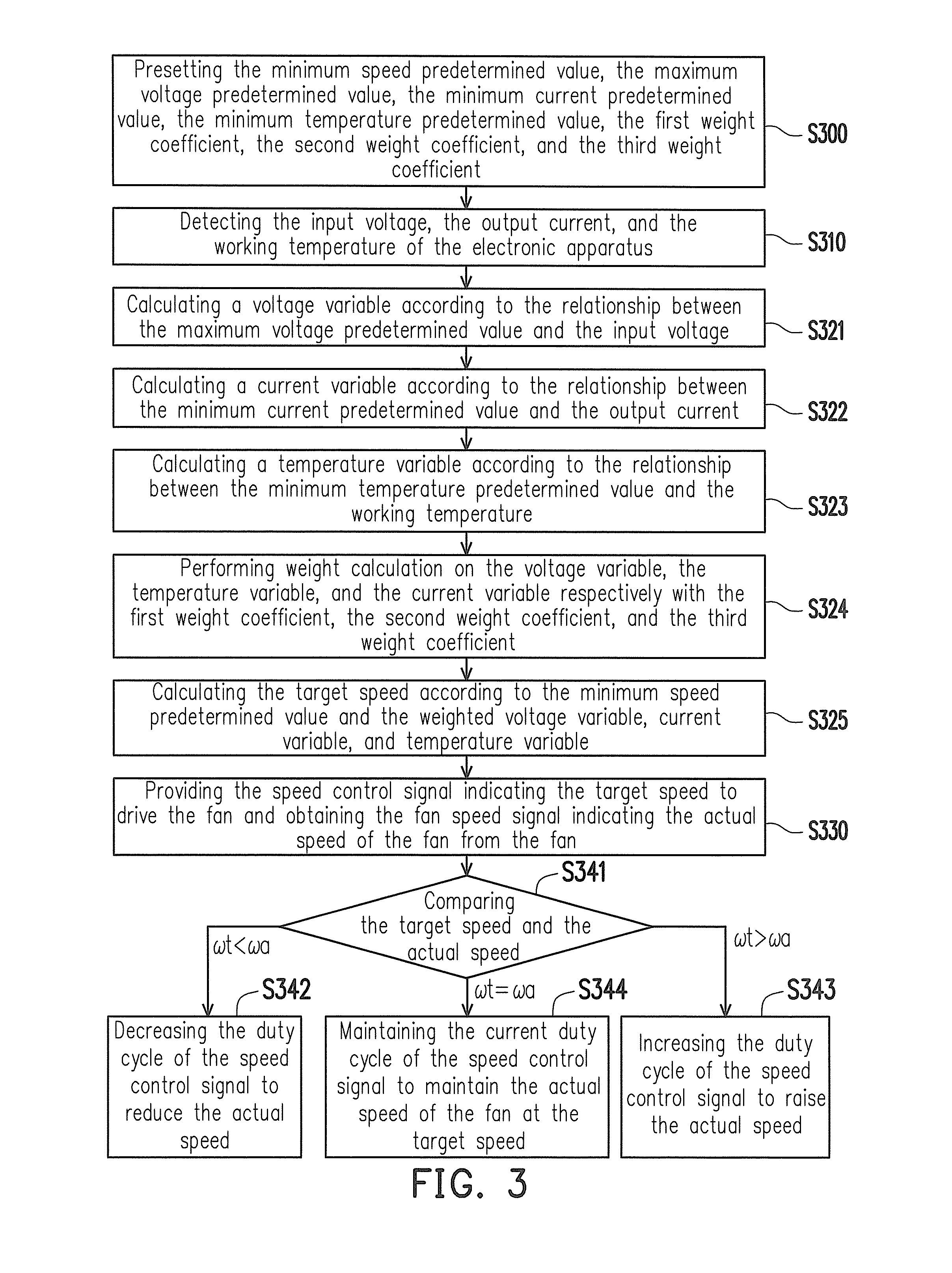
[0032]An embodiment of the invention provides a fan speed controlling method for controlling a fan speed of an electronic apparatus and the electronic apparatus using the fan speed controlling method. The fan speed controlling method is adapted for accurately calculating the fan speed required for maintaining a specific working temperature according to variables, i.e. the input voltage and the output current of the power supply and the working temperature of the electronic apparatus, and performing a close-loop control accordingly, so as to stably maintain an actual speed of the fan at a target speed to improve heat dissipation efficiency of the electronic apparatus. In order to make this disclosure more comprehensible, embodiments are described below as examples of implementation of this disclosure. Moreover, elements / components / steps with the same reference numerals are used to represent the same or similar parts in the drawings and embodiments.

[0033]FIG. 1 is a schematic diagram ...


PUM


Abstract

A method for controlling a fan speed of an electronic apparatus and the electronic apparatus using the same are provided. The method includes: detecting an input voltage, an output current, and a working temperature of the electronic apparatus; calculating a target speed of the fan according to the input voltage, the output current, and the working temperature; providing a speed control signal indicating the target speed to drive the fan and obtaining a fan speed signal indicating an actual speed of the fan; and performing a close-loop control based on the fan speed signal, so that the actual speed is adjusted to the target speed.

Description

CROSS-REFERENCE TO RELATED APPLICATION[0001]This application claims the priority benefit of Taiwan application serial no. 102147212, filed on Dec. 19, 2013. The entirety of the above-mentioned patent application is hereby incorporated by reference herein and made a part of this specification.BACKGROUND OF THE INVENTION[0002]1. Field of the Invention[0003]The invention relates to a fan speed controlling method and an application thereof, and more particularly relates to a fan speed controlling method for adjusting a fan speed by predicting a temperature variation trend of an electronic apparatus and the electronic apparatus using the fan speed controlling method.[0004]2. Description of Related Art[0005]Internal parts (e.g. CPU) and / or devices (e.g. power supply) in an electronic apparatus are usually provided with heat sink devices (e.g. heat sinks and fans). Among these heat sink devices, the fan is an indispensable component because it is capable of dissipating heat generated by th...

Claims


Application Information

Patent Timeline
Patent Type & Authority Applications(United States)
IPC IPC(8): F04D27/00F04D19/00
CPCF04D19/002F04D27/004Y02B30/70
Inventor TSAI, CHIEN-LI
Owner SPI ELECTRONICS
Learn More