Projector

a projector and projector body technology, applied in the field of projectors, can solve the problems of shortening the product life of the light source lamp, easy blackening, etc., and achieve the effects of increasing the flow rate of cooling fluid, increasing the flow rate, and increasing the flow ra

Inactive Publication Date: 2013-10-03
SEIKO EPSON CORP
View PDF7 Cites 3 Cited by
  • Summary
  • Abstract
  • Description
  • Claims
  • Application Information

AI Technical Summary

Benefits of technology

[0026]It should be noted that gradually increasing the flow rate of the cooling fluid includes increasing the flow rate in a stepwise manner and increasing the flow rate as the time elapses linearly or in a curved manner based on a predetermined function.
[0027]Here, if the rotational speed (the number of revolutions per unit time) of the fan rapidly increases, the wind noise due to the drive of the fan becomes large to thereby make the noise thus generated larger.
[0028]In contrast, according to the above configuration, since the drive of the fan is controlled so that the flow rate of the cooling fluid gradually increases, it results that the rotational speed of the fan is gradually increased. According to this process, the noise due to the drive of the fan can be reduced compared to the case in which the rotational speed of the fan rapidly increases.

Problems solved by technology

In such a state, it becomes difficult for the halogen cycle, in which the tungsten evaporated from the electrode returns to the electrode, to appropriately function, and thus it becomes easy for the blackening, in which the tungsten is attached to the inner wall of the light emitting tube, to occur.
Such blackening lowers the luminance of the light source lamp to thereby shorten the product life of the light source lamp.

Method used


Image

  • Projector
  • Projector
  • Projector

Examples


first embodiment

[0037]A first embodiment of the invention will hereinafter be explained with reference to the accompanying drawings.

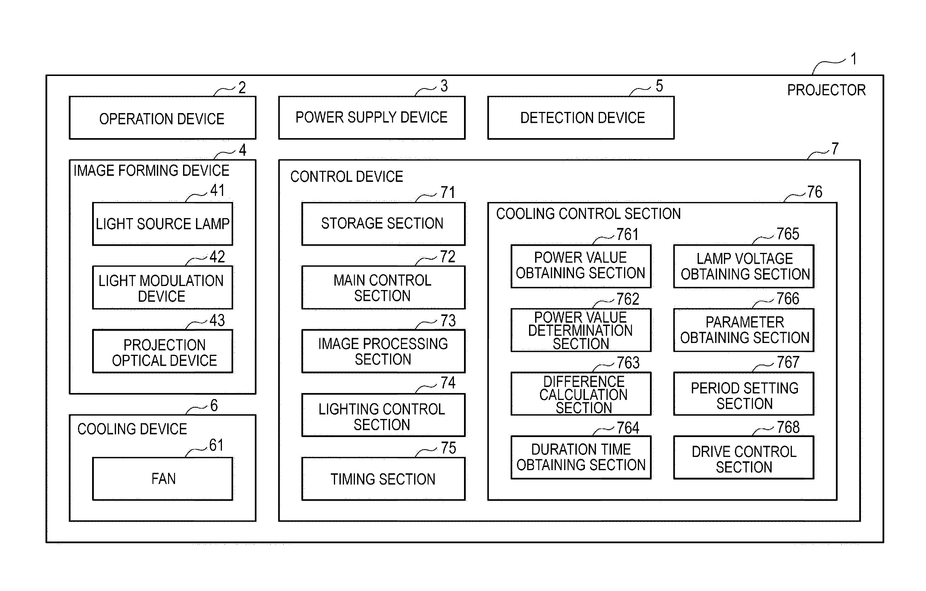
[0038]FIG. 1 is a block diagram showing a configuration of a projector 1 according to the present embodiment.

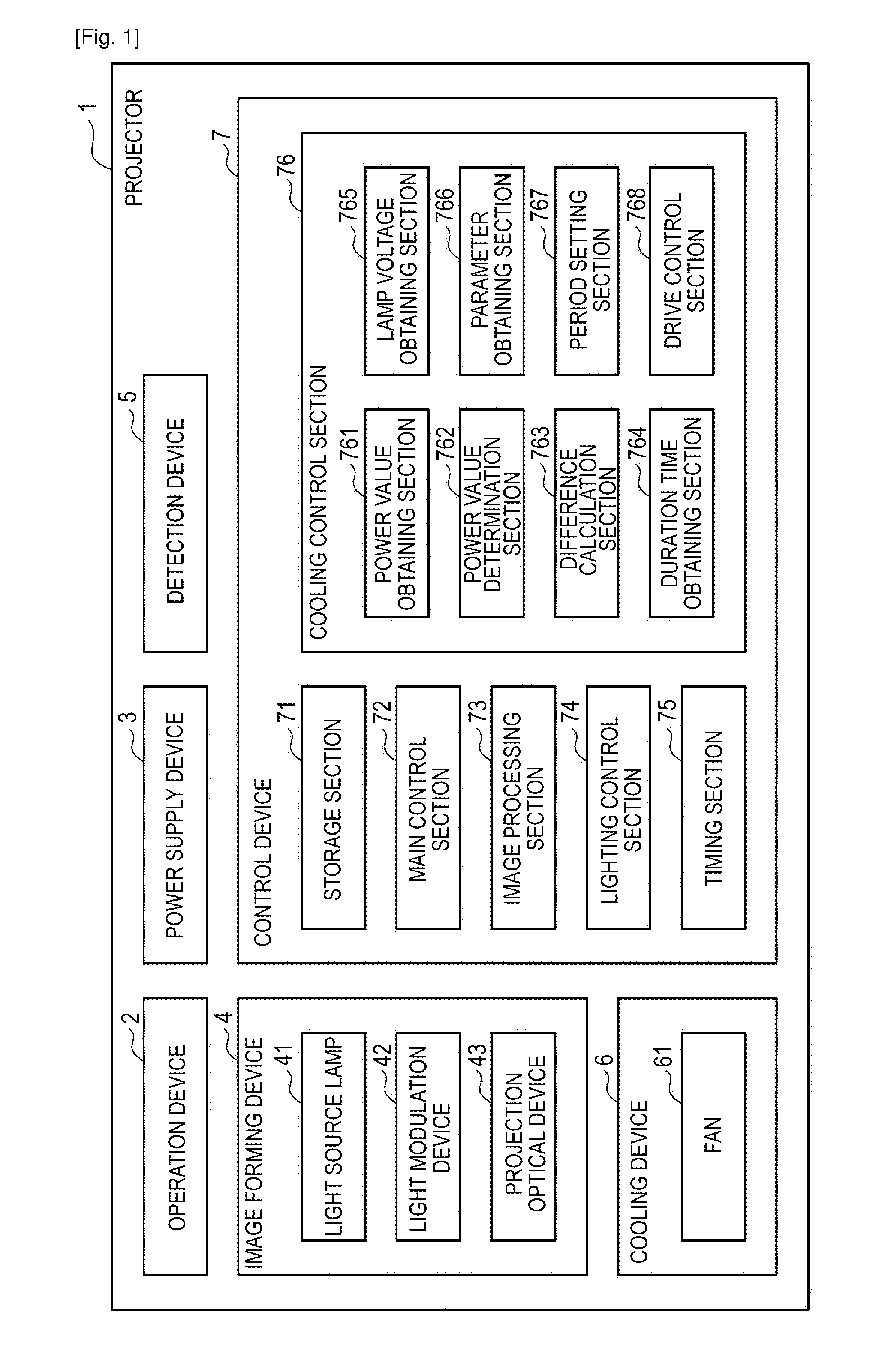
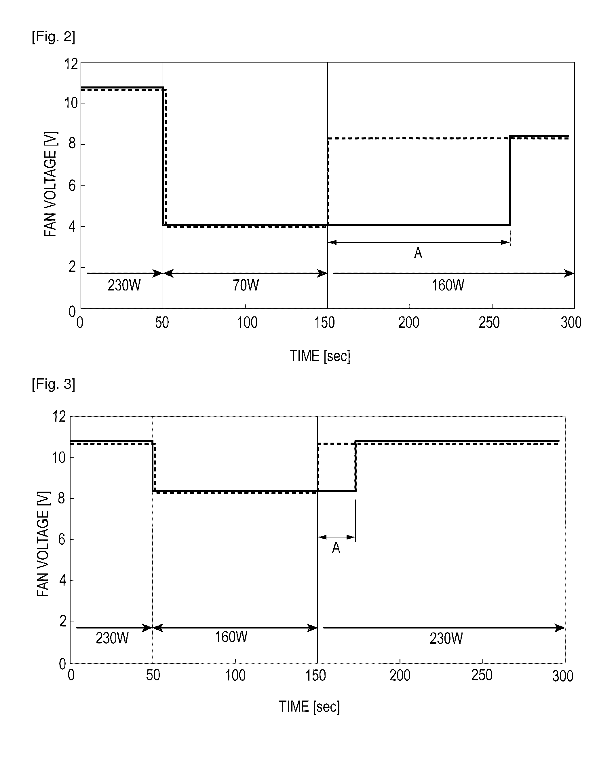
[0039]The projector 1 according to the present embodiment modulates the light beam emitted from a light source lamp 41 to thereby from an image corresponding to image information, and then projects the image on the projection target surface such as a screen in an enlarged manner. When the electric power value (hereinafter abbreviated as a “lamp electric power value” in some cases) of the lamp electric power supplied to the light source lamp 41 is raised, the projector 1 feeds cooling air at a flow rate lower than a set flow rate set in advance in accordance with a high electric power value to the light source lamp 41 for a predetermined period of time after the electric power value has been switched to thereby promptly perform rise in temperature of the light so...

second embodiment

[0125]Hereinafter, a second embodiment of the invention will be explained.

[0126]The projector according to the present embodiment is provided with substantially the same configuration as that of the projector 1 described above. Here, in the projector 1, the drive control section 768 controls the operation of the cooling device 6 based on the drive parameter corresponding to the previous power value for the delay period. In contrast, the projector according to the present embodiment is provided with a halt period for halting the operation of the cooling device 6 in the delay period, and in addition, controls the operation of the cooling device 6 so that the cooling air fed to the light source lamp 41 gradually increases. The projector according to the present embodiment and the projector 1 are different from each other in this point. It should be noted that in the explanation below, the part the same or substantially the same as the part having already been explained is denoted with ...


PUM


Abstract

A projector includes a light source lamp, a cooling device adapted to feed a cooling fluid to the light source lamp to thereby cool the light source lamp, a lighting control section adapted to supply the light source lamp with the lamp electric power having either one of a first electric power value and a second electric power value higher than the first electric power value to thereby light the light source lamp, and a cooling control section adapted to control the cooling device, and the cooling control section controls the cooling device so that the cooling fluid at a flow rate lower than a set flow rate set in accordance with the second electric power value is fed to the light source lamp during a predetermined period after the lamp electric power is switched from the first electric power value to the second electric power value.

Description

TECHNICAL FIELD[0001]The present invention relates to a projector.BACKGROUND ART[0002]In the past, there has been known a projector, which modulates a light beam emitted from a light source to thereby form an image corresponding to image information, and project the image on a projection target surface such as a screen in an enlarged manner. As such a light source, there is often used a light source lamp (a light emitting tube) such as a super-high pressure mercury lamp provided with a light emitting tube having a discharge space inside with a pair of electrodes and a light emitting substance encapsulated.[0003]Here, in the rated lighting state in which the light source lamp is lighted at the rated power, the mercury in the discharge space exists in the form of vapor. It can be said that this state is a state exceeding a saturation threshold level. In contrast, in the case of, for example, displaying a dark image, if the lamp electric power is reduced to thereby decrease the luminan...

Claims


Application Information

Patent Timeline
Patent Type & Authority Applications(United States)
IPC IPC(8): G03B21/16
CPCG03B21/16H04N9/3144H04N9/3197
Inventor TERASHIMA, TETSUOHINO, SHUNSUKE
Owner SEIKO EPSON CORP
Why Eureka
Try Eureka