
Touch module and touch display device using the touch module

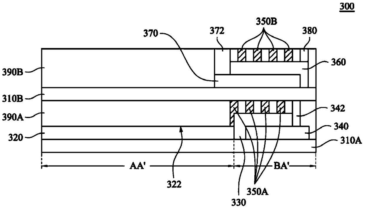
A touch module and touch sensing technology, applied in the input/output process of data processing, instruments, calculations, etc., can solve problems such as unseen methods and inconvenience, and achieve the effect of prolonging life.

Active Publication Date: 2018-11-27
INTERFACE OPTOELECTRONICS SHENZHEN +1
View PDF4 Cites 0 Cited by
  • Summary
  • Abstract
  • Description
  • Claims
  • Application Information

AI Technical Summary

Problems solved by technology

[0004] It can be seen that the above-mentioned existing structure obviously still has inconvenience and defects, and needs to be further improved.
In order to solve the above problems, relevant fields have tried their best to find a solution, but there has been no suitable way for a long time.

Method used


Image

  • Touch module and touch display device using the touch module
  • Touch module and touch display device using the touch module
  • Touch module and touch display device using the touch module

Examples


Embodiment Construction

[0068] A number of embodiments of the present invention will be disclosed below with the accompanying drawings. For the sake of clarity, many practical details will be described together in the following description. It should be understood, however, that these practical details should not be used to limit the invention. That is, in some embodiments of the present invention, these practical details are unnecessary. In addition, for the sake of simplifying the drawings, some well-known and commonly used structures and elements will be drawn in a simple and schematic manner in the drawings.

[0069] When an element is referred to as being "on", it can generally mean that the element is directly on other elements, or there may be other elements present in between. Conversely, when an element is referred to as being "directly on" another element, it cannot have the other element in between. As used herein, the word "and / or" includes any combination of one or more of the associated...


PUM


Abstract

The invention relates to a touch module. The touch module comprises a substrate, a touch sensing film, an insulation layer, a shielding layer and a plurality of conductive rail lines. The insulation layer is arranged on a peripheral region of the substrate; the shielding layer is arranged between the substrate and the insulation layer; and the conductive rail lines are arranged on the insulation layer. By arranging the insulation layer and the shielding layer between the conductive rail lines and the substrate, electric noises generated by external electromagnetic waves at the touch module can be weakened or reduced, so that the touch module is protected and the service life of the touch module is prolonged.

Description

technical field [0001] The invention relates to a touch module, in particular to a touch module with frame noise protection. Background technique [0002] Today, with the abundance of electronic devices, electromagnetic waves emitted from sources such as the electronic devices themselves or power cables will interfere with each other, making electronic devices not only have to deal with the default signal transmitted from the signal source, but also need to deal with electromagnetic interference (electromagnetic interference, EMI) additional electronic noise, the additional noise may even shorten the life of the electronic device or destroy the electronic device. Of course, this problem also occurs on touch display devices with touch modules, because the touch modules need wires located in the border area to receive signals from the detection area or active area. The small current signal received by the wire is converted into other signals for judging the touch position, so...

Claims


Application Information

Patent Timeline
Patent Type & Authority Patents(China)
IPC IPC(8): G06F3/041
Inventor 陈彦华曾启源
Owner INTERFACE OPTOELECTRONICS SHENZHEN
Learn More