Pulse width modulation (PWM) control device and driving method thereof

A technology of pulse width modulation and control device, which can be applied to controllers with pulse train output signals, electric controllers, etc., and can solve the problem of high loss rate

Active Publication Date: 2011-03-23
GIGA BYTE TECH CO LTD
View PDF0 Cites 0 Cited by
  • Summary
  • Abstract
  • Description
  • Claims
  • Application Information

AI Technical Summary

Problems solved by technology

In addition, when a driving circuit is damaged, the PWM device 110 can only enable the damaged first-phase driving circuit. For example, when the third or fourth phase is damaged, only the second or third phase can be used in sequence. Mutually
So the loss rate becomes higher for other phase numbers

Method used


Image

  • Pulse width modulation (PWM) control device and driving method thereof
  • Pulse width modulation (PWM) control device and driving method thereof
  • Pulse width modulation (PWM) control device and driving method thereof

Examples


Embodiment Construction

[0012] In order to make the above-mentioned purpose, features and advantages of the present invention more obvious and easy to understand, the preferred embodiments are specifically cited below, together with the accompanying drawings, and are described in detail as follows:

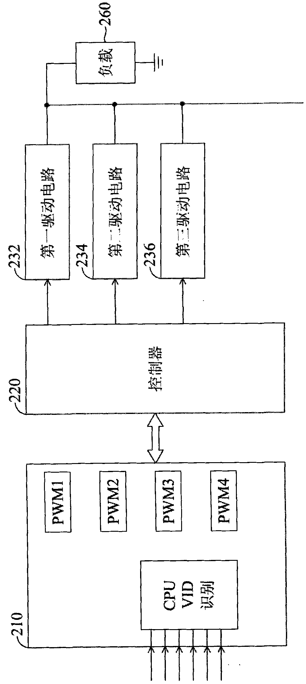
[0013] figure 2 A structural diagram illustrating a pulse width modulation (PWM) control device according to an embodiment of the present invention. The PWM control device includes a PWM device 210 and a controller 220 .

[0014] PWM device 210 is a chip, integrated circuit or microprocessor that provides multi-phase PWM signals. The controller 220 is connected to the PWM device 210 and the array drive circuit, receives the PWM signal from the PWM device 210, and transmits it to the controlled first drive circuit 232, second drive circuit 234, and third drive circuit 236 after calculation and processing, respectively. To achieve the control purpose of the present invention. The controller 220 may als...


PUM


Abstract

The invention relates to a pulse width modulation (PWM) control device and a driving method thereof. The PWM control device comprises a PWM device and a controller, wherein the PWM control device provides a plurality of PWM signals; the controller is electrically connected with the PWM device and a plurality of driving circuits, and controls a PWM signal to randomly enable a plurality of driving circuits or prohibit energy on a plurality of driving circuits according to the loading connected with a plurality of driving circuits; and when the driving circuits are damaged, the controller prohabits energy on the damaged driving circuit and randomly selects other driving circuit to replace the damaged driving circuit.

Description

technical field [0001] The present invention relates to a control device, in particular to a pulse width modulation control device. Background technique [0002] Architecture diagram of traditional PWM control circuit, such as figure 1 As shown, a PWM device 110 and driving circuits 132 and 134 are included. In a general PWM chip or device 110 , the switching of phase numbers is sequentially increasing and decreasing, and the PWM output phases are output in a fixed order. When the load is heavy, most of the driving circuits are responsible for the current output, and when the load is light, the fixed small number of driving circuits share the current output, resulting in these fixed small number of driving circuits will always be in the situation of load current output. For example, 4-phase PWM output can only be switched from 4 phases to 3 phases and then to 2 phases, or from 2 phases to 3 phases and then to 4 phases. When using 2 phases, select phases 1-2, when using 3 ...

Claims


Application Information

Patent Timeline
Patent Type & Authority Applications(China)
IPC IPC(8): G05B11/28
Inventor 廖哲贤洪如怡
Owner GIGA BYTE TECH CO LTD
Why Eureka
Try Eureka