
A modeling method of hollow blade with truss-type inner cavity stiffener structure

A hollow blade and modeling method technology, applied in the field of blade design, can solve the problems of large calculation errors in the position and shape of the stiffener truss, failure to ensure smooth transition of stiffeners, and complicated and cumbersome calculations

Inactive Publication Date: 2018-07-03
NORTHWESTERN POLYTECHNICAL UNIV
View PDF4 Cites 0 Cited by
  • Summary
  • Abstract
  • Description
  • Claims
  • Application Information

AI Technical Summary

Problems solved by technology

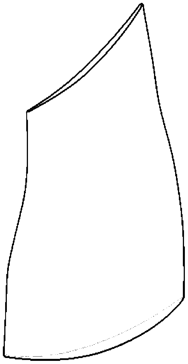
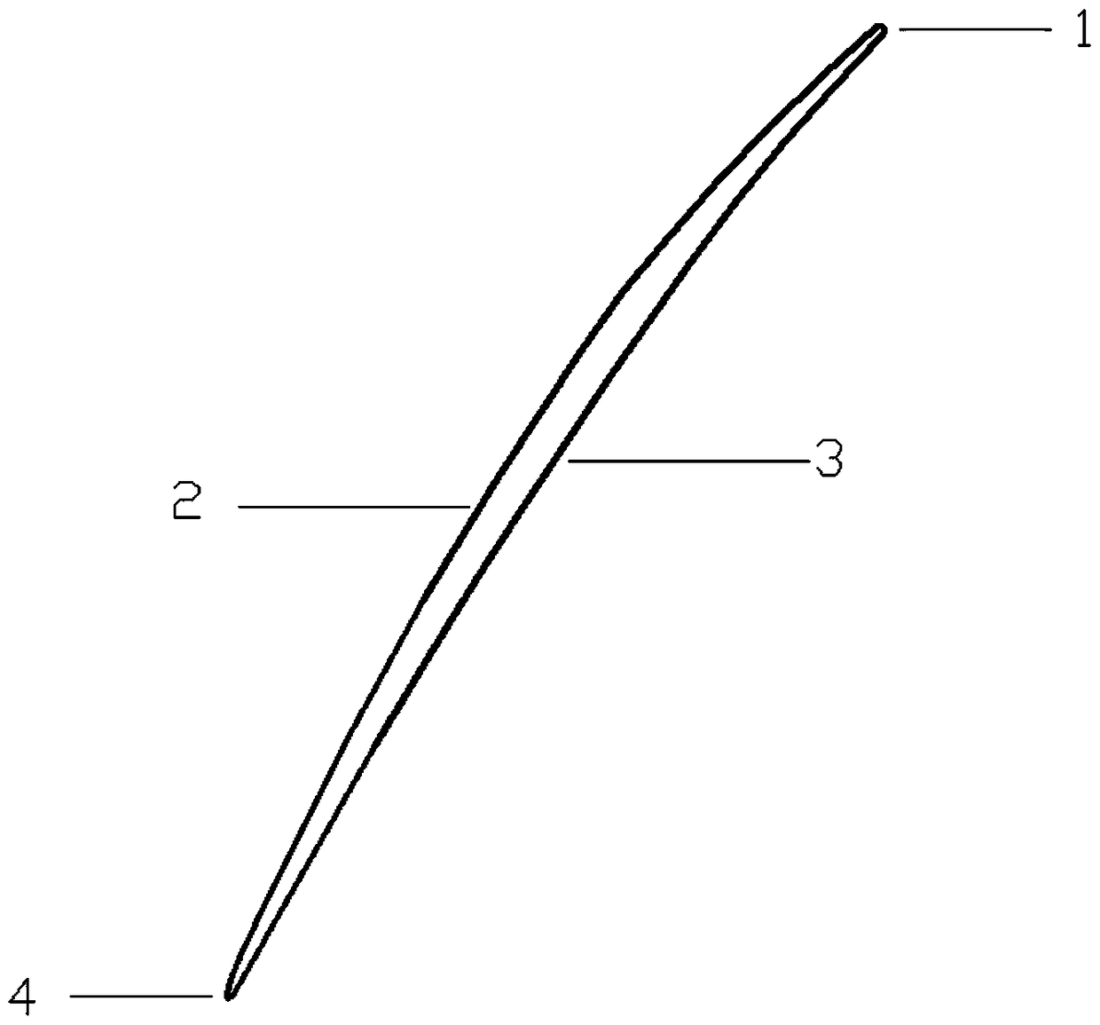
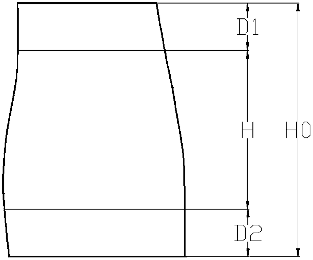
[0004] In order to solve the problem of large calculation errors in the position and shape of the rib truss in the existing truss-type hollow blade design, the calculation is complicated and cumbersome, and the smooth transition of the rib from the top section to the bottom section, and the smooth transition from both ends of the leading edge and trailing edge to the rib truss cannot be guaranteed. and other problems, the present invention proposes a hollow blade modeling method with a truss-type inner cavity stiffener structure, which constructs a 3D model of the outer shape and inner shape of the blade airfoil, and then constructs a smooth Rib entity, and the final Boolean difference operation to obtain the final hollow blade

Method used


Image

  • A modeling method of hollow blade with truss-type inner cavity stiffener structure
  • A modeling method of hollow blade with truss-type inner cavity stiffener structure
  • A modeling method of hollow blade with truss-type inner cavity stiffener structure

Examples


Embodiment Construction

[0060] Embodiments of the present invention are described in detail below, examples of which are shown in the drawings, wherein the same or similar reference numerals designate the same or similar elements or elements having the same or similar functions throughout. The embodiments described below by referring to the figures are exemplary and are intended to explain the present invention and should not be construed as limiting the present invention.

[0061] This embodiment is a modeling method for a certain type of hollow blade with a truss-type inner cavity stiffener structure, and the number of S-shaped rib trusses is 6 as an example in the figure.

[0062] This embodiment runs under the UG NX software environment. By constructing the 3D model of the blade, the inner airfoil is divided, and then the stiffener entity is constructed within the scope of the inner airfoil, and finally the final hollow blade is obtained by Boolean difference operation.

[0063] The specific step...


PUM


Abstract

The present invention proposes a hollow blade modeling method with a truss-type inner cavity stiffener structure. By constructing a 3D model of the outer shape and inner shape of the blade body, and then constructing a smooth stiffener entity within the hollow range of the inner shape blade body, and finally The Boolean difference operation obtains the final hollow blade. This method solves the problem of large calculation errors in the position and shape of the stiffener truss in the existing truss-type hollow blade design, complicated and cumbersome calculations, the inability to ensure the smooth transition of the stiffener from the top section to the bottom section, and the two ends of the leading edge and trailing edge to the stiffener truss. Smooth transition and other issues, by using this method, a more accurate layout of the stiffener truss can be obtained under low computer hardware conditions. Moreover, the method has no limitation on the platform of the three-dimensional software, and the method can be used to design the truss-type hollow blade on various software platforms.

Description

technical field [0001] The invention relates to the technical field of blade design, in particular to a modeling method for a hollow blade with a truss-type inner cavity stiffener structure. Background technique [0002] Truss-type hollow blades are mainly used for wide-chord hollow blades, which have the advantages of increasing compressor surge margin, resisting foreign object damage, increasing engine thrust, reducing the number of blades and reducing weight. In the structural design of the hollow blade, the structural form and size of the inner cavity and the layout of the inner reinforced core plate have an important influence on the structural performance of the hollow blade. The design process of the truss-type hollow blade is very complicated. The ribs are located in the hollow area of ​​the blade body. The upper end, the bottom end, the leading edge, and the trailing edge must be integrated with the blade body. The surface changes lead to complex calculation deriva...

Claims


Application Information

Patent Timeline
Patent Type & Authority Patents(China)
IPC IPC(8): G06F17/50G06T17/00
Inventor 莫蓉邢丽民李璐
Owner NORTHWESTERN POLYTECHNICAL UNIV
Learn More