Motor for reducing polar-frequency radial electromagnetic exciting force and slot-frequency radial electromagnetic exciting force

A technology of electromagnetic excitation force and slot frequency, which is applied to the static parts of the magnetic circuit, the shape/style/structure of the magnetic circuit, etc. The problem is to achieve uniform radial electromagnetic excitation force, reduce stator electromagnetic excitation force, and reduce vibration.

Active Publication Date: 2016-02-03
TSINGHUA UNIV
View PDF6 Cites 4 Cited by
  • Summary
  • Abstract
  • Description
  • Claims
  • Application Information

AI Technical Summary

Problems solved by technology

These two types of electromagnetic exciting forces are caused by the nature of the motor, and it is extremely difficult to reduce and weaken these electromagnetic exciting forces
At present, methods such as reducing magnetic density, chute or closed slot are often used, but the result is either that the volume, weight and cost of the motor increase, or the effect is not obvious
So far, there is no better solution to motor vibration and noise

Method used


Image

  • Motor for reducing polar-frequency radial electromagnetic exciting force and slot-frequency radial electromagnetic exciting force
  • Motor for reducing polar-frequency radial electromagnetic exciting force and slot-frequency radial electromagnetic exciting force
  • Motor for reducing polar-frequency radial electromagnetic exciting force and slot-frequency radial electromagnetic exciting force

Examples


Embodiment Construction

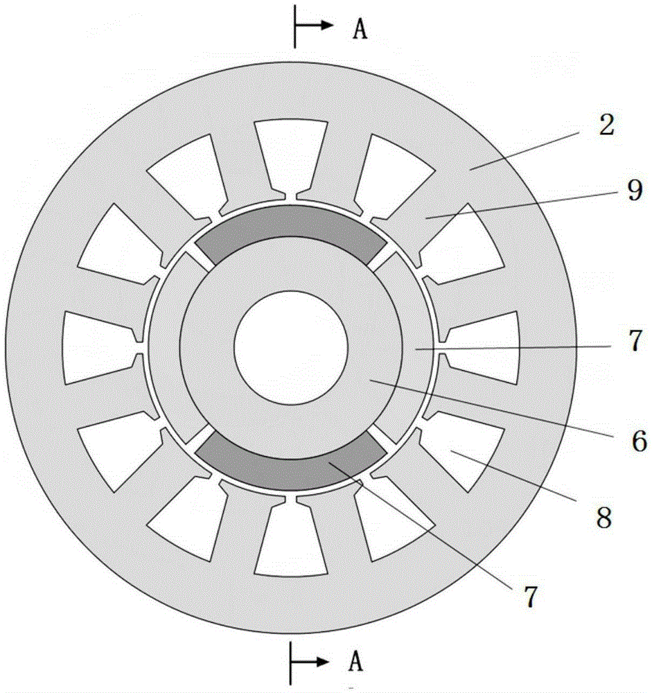
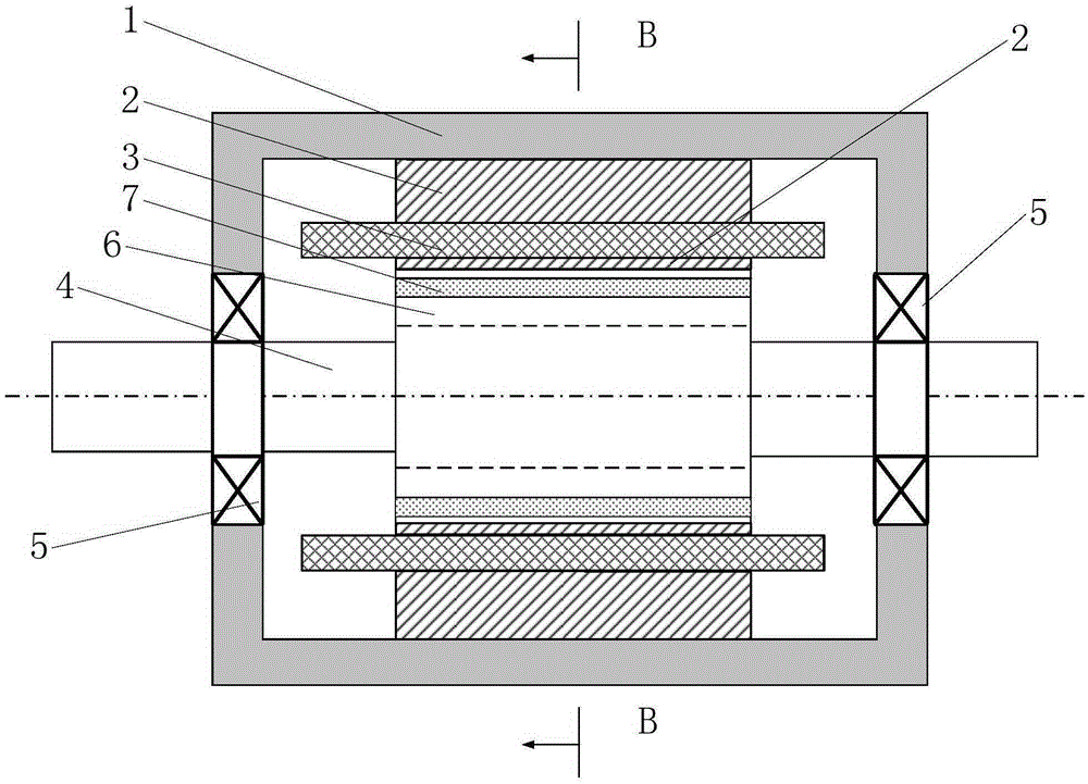
[0031] Such as figure 1 , figure 2 As shown, the existing common motor includes a stator frame 1, a stator core 2, a stator winding 3, a rotor shaft 4, a bearing 5, a rotor core 6 and a permanent magnet 7; wherein, the stator frame 1 can adopt a conventional motor The installation method is fixed, and the stator core 2 is a part of the magnetic circuit of the motor. A stator core 2 is fixedly installed in the stator frame 1, and a slot 8 is opened on the inner circle of the stator core 2. The stator winding 3 is arranged in the slot 8. The stator winding 3 is generally a three-phase winding, and the two sides of the slot 8 are teeth 9. . The rotor shaft 4 is fixedly arranged in the stator frame 1 through the bearing 5, and the rotor core 6 is fixedly arranged on the rotor shaft 4. The permanent magnet 7 is arranged on the rotor iron core 6. The magnetization direction of the permanent magnet 7 is radial, and the permanent magnet The polarities of 7 are alternately arranged...


PUM


Abstract

The invention relates to a motor for reducing a polar-frequency radial electromagnetic exciting force and a slot-frequency radial electromagnetic exciting force. The motor comprises a stator base in which a stator core is fixedly arranged. A rotor shaft is fixedly arranged in the stator base through bearings. A rotor core is fixed on a rotor shaft. The motor is characterized in that the motor further comprises a stator permanent magnetic pole, a rotor armature winding and a collector ring; the stator permanent magnetic pole is fixed in the stator core; the stator core is arranged between the N pole and the S pole of the stator permanent magnetic pole; the outer circumference of the rotor core is provided with a plurality of troughs uniformly; the rotor armature winding is arranged in the troughs; at one side or two sides of the rotor core, a collector ring is arranged on the rotor shaft; and after each winding in the rotor armature winding is connected with the collector ring, the winding is connected with an external stationary power supply circuit through an electric brush. The motor of the invention can effectively reduce vibration between the stator core and the stator base, thereby performing a function of reducing vibration and noise.

Description

technical field [0001] The invention relates to a motor, in particular to a motor whose excitation source is located in the stator for reducing the radial electromagnetic excitation force of pole frequency and slot frequency. Background technique [0002] Modern society cannot do without motors, and motors are used in transportation, industrial and agricultural production, information processing, and various fields of daily life. There are many types of motors with different structures, such as asynchronous motors, permanent magnet motors, electric excitation motors, etc. All kinds of motors will generate vibration and noise during the rotation process. Vibration noise is a kind of environmental pollution, which will have adverse effects on people's health and daily life; vibration and noise are more important in the military field. Therefore, it is of great significance to reduce the vibration and noise of the motor. [0003] The fundamental magnetic field and a series of...

Claims


Application Information

Patent Timeline
Patent Type & Authority Applications(China)
IPC IPC(8): H02K1/17H02K1/14
Inventor 王善铭杨占录王祥珩孙旭东柴建云
Owner TSINGHUA UNIV
Why Eureka
Try Eureka