A control valve and an electric pressure cooker equipped with the valve

A technology for controlling valves and valve cores, applied in pressure cookers, kitchen utensils, household utensils, etc., can solve the problems of long time cooking, difficult boiling of food in the pot, affecting the taste of food, etc., to achieve the function of maintaining pressure and ensure the taste of food. Effect

Active Publication Date: 2017-12-15
FOSHAN SHUNDE QINGNENG ELECTRIC APPLIANCES CO LTD
View PDF6 Cites 0 Cited by
  • Summary
  • Abstract
  • Description
  • Claims
  • Application Information

AI Technical Summary

Problems solved by technology

The disadvantage of an electric rice cooker is that it can only heat food under normal pressure. For some foods that are not easy to cook, it often takes a long time to cook.
[0003] Therefore, electric pressure cooker products have appeared. Existing electric pressure cookers generally include a pot body and a pot cover. The pot cover is provided with a handle, a pressure relief valve and a safety valve. To the sealed state, with the heating of the liquid, the air pressure in the pot increases continuously, and the food is easier to cook under the high pressure state, but because the increase of the air pressure also increases the boiling point of the food, it makes it difficult for the liquid temperature to reach the boiling point and cause the food in the pot to boil. It is difficult to boil or can only boil after reaching a very high temperature, which makes the food unable to fully convect and tumble, which affects the taste of the food

Method used


Image

  • A control valve and an electric pressure cooker equipped with the valve
  • A control valve and an electric pressure cooker equipped with the valve
  • A control valve and an electric pressure cooker equipped with the valve

Examples


Embodiment 1

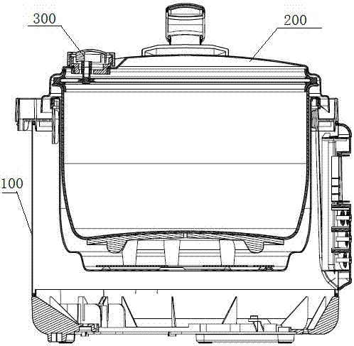
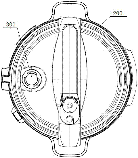
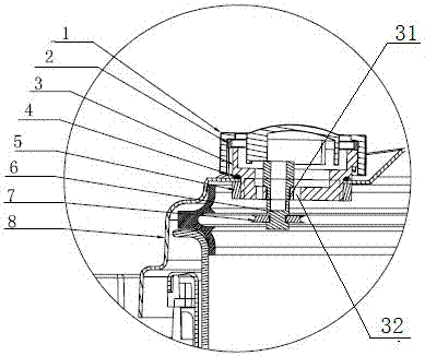
[0030] Such as Figure 1 to Figure 4 As shown, an electric pressure cooker includes a pot body 100 and a pot cover 200, the pot cover 200 is provided with a mounting hole, and a control valve 300 is embedded in the mounting hole, as image 3 , Figure 4 As shown, the control valve 300 includes a base 3 and a valve cover 1 buckled on the base 3, the base 3 and the valve cover 1 enclose a valve chamber, as Figure 9 , Figure 10 As shown, the base 3 is provided with a valve core hole 31 and an exhaust hole 32 communicating with the valve cavity, and the valve cavity is provided with a valve core 6, such as Figure 6 As shown, the spool 6 is cylindrical and includes two ends, respectively a first end 61 and a second end 62, wherein the diameter of the first end 61 is larger than the spool hole 31 on the base 3, and the second end The diameter of the portion 62 is smaller than the spool hole 31, therefore, the first end 61 of the spool 6 is located in the valve chamber, and the...

Embodiment 2

[0036] This embodiment has been further improved on the basis of Embodiment 1. The difference from Embodiment 1 is that the valve core 6 of this embodiment still includes two ends, the first end 61 is located in the valve chamber, and the second The two ends 62 protrude through the spool hole 31 , and the difference from the first embodiment is that the spool gasket 7 on the spool 6 is arranged inside the base 3 , that is, in the valve cavity.

[0037]When the bonnet 1 is rotated, the bonnet still has two positions: when it is in the first position, the spool 6 is blocked by the limit rib 12 and cannot move upwards, the pressure of the spool 6 on the limit rib 12 Move downwards so that the valve core gasket 7 is only attached to the vent hole 32 on the base, so that the air pressure in the pot body 100 cannot be discharged through the vent hole 32, and the air pressure in the pot body 1 increases, so that the food in the pot body 100 is in the Non-boiling state; when the valve...

Embodiment 3

[0040] This embodiment is partially improved on the basis of embodiment 1. The difference from embodiment 1 is that the control valve base 3 and the pot cover 200 are integrally formed in this embodiment.


PUM


Abstract

The invention provides a control valve and an electric pressure pot provided with the valve. The control valve comprises a base and a valve deck. The base and the valve deck form a valve cavity. The base is provided with a valve element hole and an exhaust hole which are communicated with the valve cavity. A valve element is arranged in the valve cavity. One end of the valve element extends out of the valve element hole of the base. A valve element gasket used for sealing the exhaust hole is arranged on the portion, close to the valve element hole, of the valve element. The valve deck is provided with a through hole communicated with the valve cavity and a limiting rib used for blocking movements of the valve element. The valve deck is provided with two stations. When the valve deck is located at the first station, the valve element is blocked by the limiting rib, and the valve element gasket is far away from the exhaust hole; when the valve deck is located at the second station, the limiting rib is far away from the valve element, and the valve element gasket plugs the exhaust hole. Or, when the valve deck is located at the first station, the valve element is blocked by the limiting rib and the valve element gasket plugs the exhaust hole; when the valve deck is located at the second station, the limiting rib is far away from the valve element. By means of cooperation of the valve element, the valve element gasket, the exhaust hole and the valve deck, the control valve can achieve the sealing and ventilation functions.

Description

technical field [0001] The invention relates to the field of electric pressure cookers, more specifically, to a control valve for electric pressure cookers. Background technique [0002] The current electric rice cooker has no function of pressurizing or maintaining pressure, so the air pressure inside the pot is basically consistent with the pressure outside the pot. Therefore, when cooking food, the temperature inside the pot can easily reach the boiling point of the food, and the food is fully convected under the action of boiling. Tumbling makes food more evenly heated and more nutritious. The disadvantage of an electric rice cooker is that it can only heat food under normal pressure. For some foods that are not easy to cook, it often takes a long time to cook. [0003] Therefore, electric pressure cooker products have appeared. Existing electric pressure cookers generally include a pot body and a pot cover. The pot cover is provided with a handle, a pressure relief val...

Claims


Application Information

Patent Timeline
Patent Type & Authority Patents(China)
IPC IPC(8): A47J27/092A47J27/08
Inventor 黄树才
Owner FOSHAN SHUNDE QINGNENG ELECTRIC APPLIANCES CO LTD
Why Eureka
Try Eureka