
A pressure-maintaining automatic internal support fixture and clamping method

An inner support fixture and pressure-holding technology, applied in the direction of expanding the mandrel, can solve the problem of inability to guarantee the local rigidity of the thin-walled parts processing area, and achieve the effect of simple structure, uniform inner support and large driving force.

Active Publication Date: 2021-04-20
DALIAN UNIV OF TECH
View PDF9 Cites 0 Cited by
  • Summary
  • Abstract
  • Description
  • Claims
  • Application Information

AI Technical Summary

Problems solved by technology

However, in this structure, there is still a large gap between the adjacent wedges after they are propped up, and the local rigidity of the thin-walled parts processing area cannot be guaranteed.

Method used


Image

  • A pressure-maintaining automatic internal support fixture and clamping method
  • A pressure-maintaining automatic internal support fixture and clamping method
  • A pressure-maintaining automatic internal support fixture and clamping method

Examples


Embodiment Construction

[0023] Embodiments of the present invention will be described in detail below in conjunction with the accompanying drawings and technical solutions.

[0024] In the embodiment, the thin-walled cylindrical member 19 is made of 406A high-strength steel, with a diameter of 1000mm and a total length of 1800mm. It is formed by overall segmental spinning, and the wall is thin and uneven (the wall thickness of the front and rear cylindrical sections is only 3.5mm, and the wall thickness of the middle area to be processed is 8mm); the profile error is large, and the straightness error of the busbar in the middle area to be processed is only 1~3mm; the length of the area to be processed is 640mm, and its distance from the bottom surface of the workpiece is 520mm.

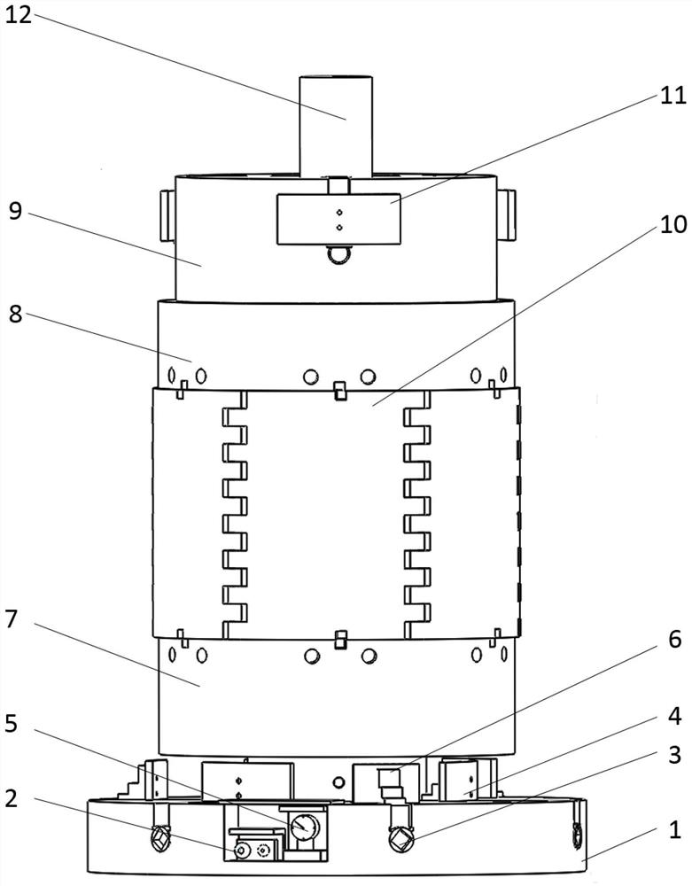
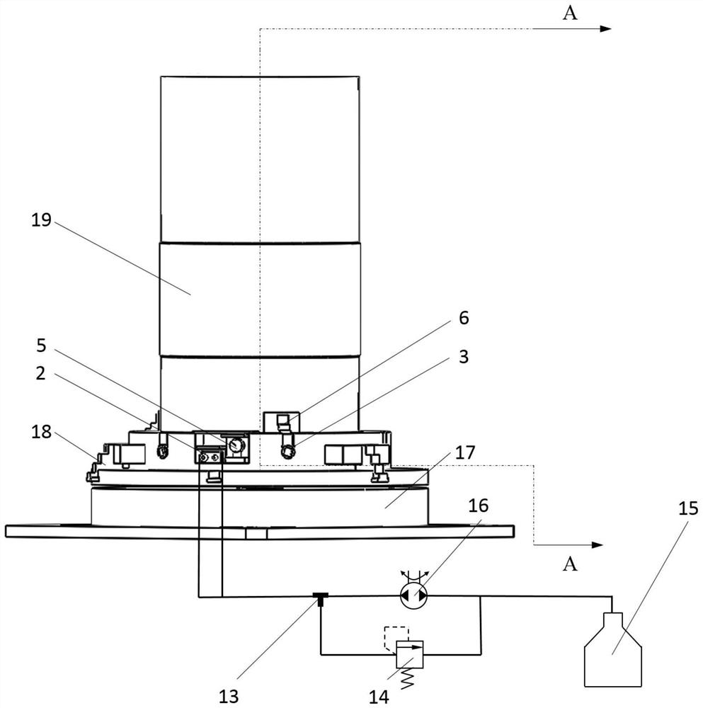
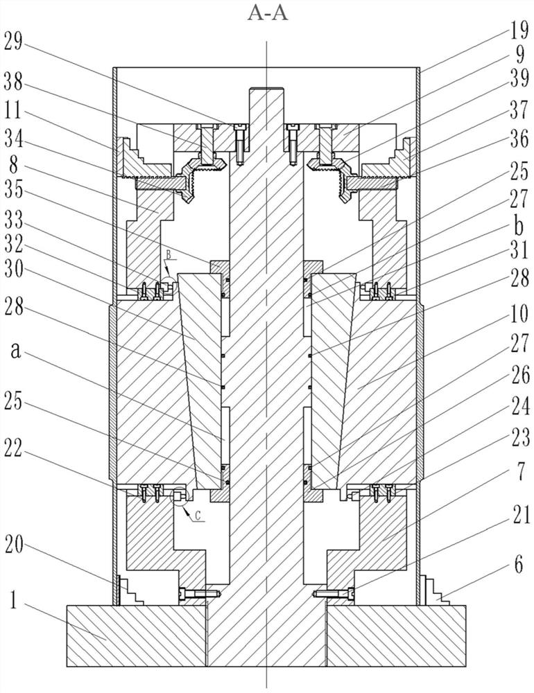
[0025] First, assemble the pressure-holding type automatic inner support fixture equipment, as attached figure 1 , 2 , 3 shown. The fixture is composed of a positioning clamping device, an auxiliary device, and a hydrauli...


PUM


Abstract

The invention relates to a pressure-maintaining type automatic internal support fixture and a clamping method, which belong to the technical field of clamping, and relate to a pressure-maintaining type automatic internal support fixture and a clamping method. The internal support fixture is composed of a positioning clamping device, an auxiliary device, and a hydraulic drive system. The clamping method clamps the workpiece vertically, uses the hydraulic system to deliver the hydraulic oil to the clamping chamber and the loosening chamber, drives the piston to move, and then makes the inner expansion sleeve move radially to prop up the workpiece. The inner expansion sleeve is multi-lobed, and the side is serrated. Adjacent inner expansion sleeves can be meshed. The structure is simple, which can achieve uniform tension and improve the local rigidity of the workpiece. The combination of claws and rubber plates is used to provide auxiliary support for the upper and lower unprocessed areas of the workpiece to ensure the overall rigidity of the workpiece. The connection valve is used to control the clamping and loosening of the fixture, and the operation is convenient. The connecting valve can keep the clamping path without pressure leakage for a long time after the oil pressure source is cut off, and realize the pressure maintaining function. It can realize flexible, fast and reliable clamping of thin-walled cylindrical parts.

Description

technical field [0001] The invention belongs to the field of clamping technology, and in particular relates to a pressure-maintaining type automatic internal support clamp and a clamping method. Background technique [0002] Thin-walled parts are widely used in the aerospace field due to their light weight, compact structure, and material saving. However, their rigidity is poor, their strength is weak, and they are prone to deformation under the action of clamping force and cutting force. Therefore, it is necessary to ensure high reliable clamping . In the existing clamping methods, the outer surface or inner surface of the thin-walled part is used as the positioning reference plane, and the three-jaw chuck or the elastic expansion sleeve with its own centering function is used for positioning and clamping. However, this method cannot make the support surface of the fixture fully contact with the surface of the workpiece, and it is difficult to ensure the local stiffness of...

Claims


Application Information

Patent Timeline
Patent Type & Authority Patents(China)
IPC IPC(8): B23B31/40
CPCB23B31/402
Inventor 王永青张发亮刘海波李特王成龙刘阔吴军贾振元
Owner DALIAN UNIV OF TECH
Learn More