
Power tool and rotary impact tool

一种电动工具、冲击工具的技术,应用在转动冲击工具领域,能够解决元件不良影响等问题,达到结构紧凑、抑制振动传递给控制电路基板的效果

Active Publication Date: 2016-02-10
MAKITA CORP
View PDF11 Cites 12 Cited by
  • Summary
  • Abstract
  • Description
  • Claims
  • Application Information

AI Technical Summary

Problems solved by technology

[0006] In the impact screwdriver of Patent Document 1, since the circuit board is housed in the lower end of the handle connected to the motor case, the vibration generated by the driving part connected to the motor is transmitted to the circuit board through the handle, and the length of the circuit board is Vibrations over time may have adverse effects on components mounted on circuit boards, etc.

Method used


Image

  • Power tool and rotary impact tool
  • Power tool and rotary impact tool
  • Power tool and rotary impact tool

Examples


no. 1 Embodiment approach

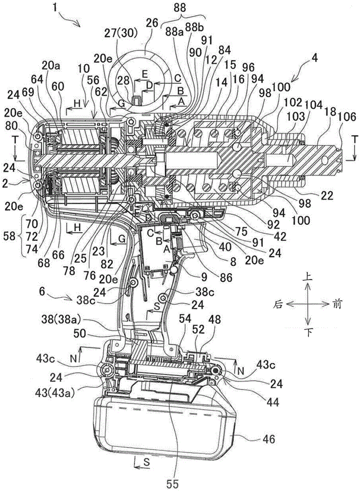
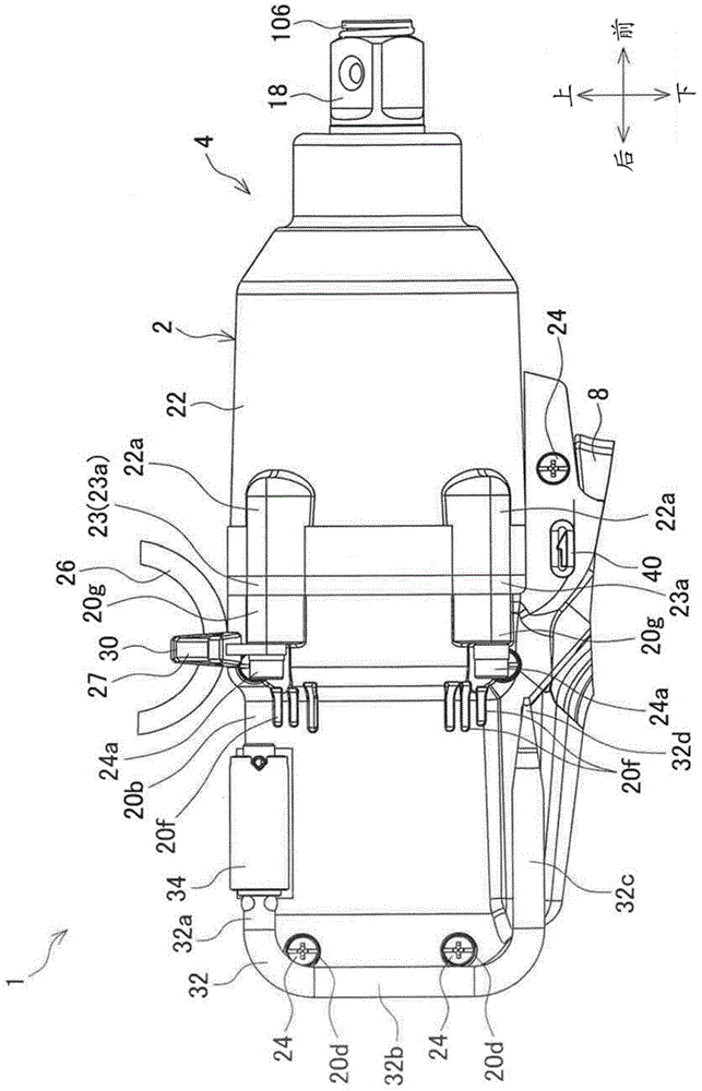
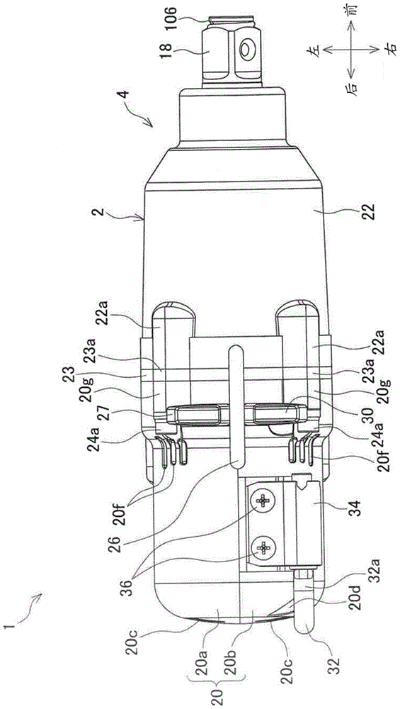
[0061] figure 1 It is a central longitudinal sectional view of a cordless impact wrench (rotary impact tool) 1 as an example of the electric tool according to the first embodiment of the present invention, figure 2 It is a partial right view of the impact wrench 1, image 3 Is a top view of the impact wrench 1. Figure 4 It is a top view and a horizontal cross-sectional view (cut along the line T-T) of the impact wrench 1, Figure 5 Yes figure 1 Partial rear view of the cordless impact wrench in Image 6 Is along figure 1 A partial cross-sectional view cut along the A-A line, Figure 7 Is along figure 1 A partial cross-sectional view cut along the line B-B in Picture 8 Is along figure 1 A partial cross-sectional view cut along the C-C line, Picture 9 Is along figure 1 A partial cross-sectional view cut by the D-D line in Picture 10 Is along figure 1 A partial cross-sectional view of the E-E line in Picture 11 Is a cross-sectional view cut along the G-G line, Picture 12 Is alo...

no. 2 Embodiment approach

[0148] Figure 19 Is the equivalent of the impact wrench 111 according to the second embodiment of the present invention figure 1 The figure, Figure 20 Is the equivalent of the impact wrench 111 according to the second embodiment of the present invention Figure 4 The figure, Figure 21 Is the equivalent of the impact wrench 111 according to the second embodiment of the present invention Figure 7 Graph (along Figure 19 BB-BB line cut section view), Figure 22 Is the equivalent of the impact wrench 111 according to the second embodiment of the present invention Picture 8 Graph (along Figure 19 The cross-sectional view of CC-CC line), Figure 23 Is the equivalent of the impact wrench 111 according to the second embodiment of the present invention Figure 13 Figure.

[0149] The impact wrench 111 of the second embodiment has the same structure as the impact wrench 1 of the first embodiment except for the planetary gear mechanism. The same components or parts of the impact wrench ...


PUM


Abstract

To provide a power tool and a rotary impact tool capable of suppressing transmission of vibration to a circuit board and so on from a drive portion connecting to a motor as a vibration generation source. An impact wrench (1) includes a motor housing (20) which houses a motor (10) or a grip housing (38), a battery holding housing (43) connecting to the motor housing (20) or the grip housing (38) through an elastic body (54) and a control circuit board (52) housed in the battery holding housing (43) for controlling the motor (10).

Description

Technical field [0001] The present invention relates to an electric tool capable of applying rotational force to an output part, and a rotational impact tool capable of applying rotational impact force to the output part. Background technique [0002] As shown in Patent Document 1 below, there is known an impact screwdriver capable of transmitting the rotation of the drive shaft of the motor after deceleration to the output shaft. [0003] In this impact screwdriver, a circuit board is housed in the lower end portion of the handle connected to the motor housing, and a battery mounting portion is provided on the lower side of the circuit board. [0004] In addition, in the impact screwdriver, the rotation of the driving shaft of the motor is reduced by a planetary gear mechanism, wherein the planetary gear mechanism is disposed between the driving shaft and the output shaft, and the planetary gear mechanism has a ring gear (internal gear) And two planetary gears. The two planetary g...

Claims


Application Information

Patent Timeline
Patent Type & Authority Applications(China)
IPC IPC(8): B25B21/02B25F5/00
CPCB25B21/02B25F5/00B25F5/006B25F5/001
Inventor 近藤友幸平林德夫
Owner MAKITA CORP
Learn More