Shifting rotational device

A technology of rotating device and rotating connection, applied in the field of mechanical parts, can solve the problems of overall appearance influence, unfavorable outer surface cleaning, etc.

Inactive Publication Date: 2016-02-10
胡国贤
View PDF4 Cites 0 Cited by
  • Summary
  • Abstract
  • Description
  • Claims
  • Application Information

AI Technical Summary

Problems solved by technology

This kind of hinge can make the objects fixed on its two leaves rotate in a certain space, but the blades and the rotating shaft sleeves are respectively located on the inner and o

Method used


Image

  • Shifting rotational device
  • Shifting rotational device
  • Shifting rotational device

Examples


Embodiment Construction

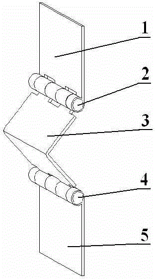
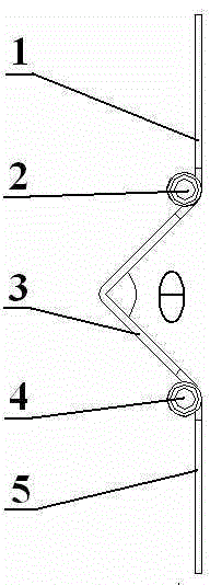
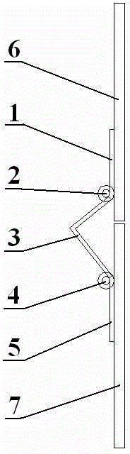
[0013] A shifting and rotating device, comprising a rotating arm A1, a rotating shaft A2, a connecting arm 3, a rotating shaft B4, and a rotating arm B5. One end of the rotating arm A1 and one end of the connecting arm 3 are provided with an adapter for the rotating shaft A1 A rotating shaft sleeve, one end of the rotating arm B5 and the other end of the connecting arm 3 are provided with rotating shaft sleeves adapted to the rotating shaft B4, and the rotating arm A1 and the connecting arm 3 can pass through the rotating shaft A2. Rotational connection, the rotating arm B5 and the connecting arm 3 are rotatably connected by the rotating shaft B4, and the connecting arm 3 is bent to form a certain angle θ .

[0014] Further, 60 degrees ≤ θ ≤120 degrees.

[0015] further, θ= 90 degrees.


PUM


Abstract

The invention provides a shifting rotational device. A product provided with the shifting rotational device has larger rotation range and is more reliable. All the parts of the shifting rotational device are arranged on inner sides of the mounted object so that the product has more beautiful appearance, and in addition, an outer surface is convenient to clean so that the product is improved in competitiveness. The shifting rotational device includes a rotating arm A, a rotating shaft A, a connection arm, a rotating shaft B and a rotating arm B. One end of the rotating arm A and one end of the connection arm are respectively provided with rotating shaft sleeves which are matched with the rotating shaft A. One end of the rotating arm B and the other end of the connection arm are respectively provided with rotating shaft sleeves which are matched with the rotating shaft B. The rotating arm A is rotatably connected to the connection arm through the rotating shaft A and the rotating arm B is rotatably connected to the connection arm through the rotating shaft B. The connection arm is bent to form a certain angle.

Description

technical field [0001] The invention relates to mechanical components, in particular to a displacement and rotation device. Background technique [0002] Most of the rotating devices in the prior art rotate around an axis, and the position of the axis center is relatively fixed during the rotation process. For example, the hinge is formed by two independent blades hinged together, and a hinged structure consisting of a rotating shaft and a rotating shaft sleeve is installed between the two blades. This kind of hinge can make the objects fixed on its two leaves rotate in a certain space, but the blades and the rotating shaft sleeves are respectively located on the inner and outer sides of the loaded objects, and some parts will always be exposed outside, which will affect the overall appearance. impact, and is not conducive to the cleaning of the outer surface. Contents of the invention [0003] In order to overcome the above-mentioned defects in the prior art, the presen...

Claims


Application Information

Patent Timeline
IPC IPC(8): F16C11/04
Inventor 胡国贤
Owner 胡国贤
Why Eureka
Try Eureka